 EN
EN


Connecting a vibration transmitter to a distributed control system looks like a simple loop, and it is precisely that simplicity which causes mistakes. A Bently Nevada transmitter 4-20 mA DCS interface has to satisfy the transmitter, the wiring, and the DCS input at the same time, and each of the three has its own documentation. This article explains what to confirm before a single conductor is landed. It states no specifications and draws no compatibility conclusion, because the authoritative references are the manufacturer's manuals, the loop drawings, and the DCS configuration records. Every check described here for a Bently Nevada transmitter 4-20 mA DCS connection exists to move the decision away from assumption and towards documented fact.
Why the 4-20 mA Loop Interface Deserves Its Own Check
The loop is the point where two systems meet, and a meeting point is where misunderstandings concentrate. The transmitter produces a signal, the DCS expects an input, and the wiring carries one to the other. Any one of the three can be documented differently, or documented not at all, and the result is a loop that appears correct on paper while behaving unexpectedly in service. A Bently Nevada transmitter 4-20 mA DCS interface should be treated as a system of three parts rather than as a single cable.
The signal itself is defined by documents rather than by convention. What the transmitter represents on the loop, how the loop is powered, and what the receiving channel interprets are all described in the transmitter literature and the DCS records. Reading both before connecting anything is the only way to know whether they agree. A Bently Nevada transmitter 4-20 mA DCS check that reads only one side is half a check.
There is also an organisational reason to slow down here. Transmitters are usually owned by the instrumentation or condition-monitoring team, while the DCS is owned by the control team, and the two groups may hold different parts of the drawing set. Establishing who holds which document is part of the work. For a Bently Nevada transmitter 4-20 mA DCS connection, the handover between teams matters as much as the wiring itself.
It also helps to separate the loop from the wider system. A monitoring loop is part of a condition-monitoring installation, and the transmitter is only its outermost element; the monitor, the protection logic, and the way alarms are used all sit behind the channel that receives the signal. Documenting the loop without reference to that wider context can leave a question open even when the wiring itself is clear. Reading the loop in its setting is what makes the comparison meaningful, and it is the setting, rather than the cable alone, that decides how a change should be approached. Where the setting has been altered since commissioning, that history belongs in the same record, because an unrecorded change is indistinguishable from an unexplained behaviour.
What to Confirm About the Loop and the DCS Input
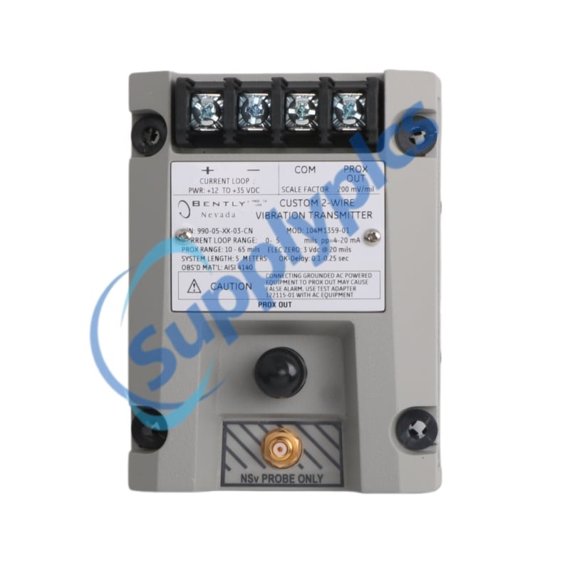
Begin with the transmitter's own documentation. It defines the loop output, the supply arrangement, and the conditions under which the output is valid, and it identifies the model by its complete ordering code. Record the full code from the nameplate, because a family name does not identify a configured transmitter. Any useful Bently Nevada transmitter 4-20 mA DCS enquiry starts from that code.
Then read the DCS side. The receiving channel has a documented input behaviour, a configuration, and a place in the I/O database, and those records describe what the channel expects and how it treats what it receives. The loop drawing ties the two halves together by identifying terminals, cores, and screens. Compare the transmitter literature, the loop drawing, and the DCS configuration, and note where they disagree. A Bently Nevada transmitter 4-20 mA DCS assessment lives or dies on that comparison.
Finally, confirm the loop as a whole. Power, polarity, termination, and the route the signal takes are all part of the design, and each element should be traceable to a document rather than to precedent from another machine. Where something is not documented, record it as a question rather than closing it by habit. A Bently Nevada transmitter 4-20 mA DCS connection that rests on undocumented assumptions is a connection waiting to be revisited.
Where the loop crosses a boundary between disciplines, the records often cross it too. A marshalling cabinet may belong to one set of drawings, the field device to another, and the control channel to a third, and each set may be maintained by a different group. The practical task is to bring those records together long enough to check them against one another, and to note which one is authoritative when they conflict. That sounds like administration, yet it is exactly the kind of administration that prevents a connection being made to a layout that only one drawing supports. Gathering the three sets into one place, even briefly, is often the single most useful step in preparing a loop for a change.
Anonymous Scenario Example
Illustrative anonymous scenario, not a Supplyplcs customer project: In June 2024, in Jakarta, Indonesia, a rotating-equipment monitoring loop was being recommissioned after a transmitter change. The loop drawing showed the field terminals and the marshalling cabinet, but the DCS configuration record had not been updated since an earlier modification. Before connecting the Bently Nevada transmitter 4-20 mA DCS wiring, the engineer collected the transmitter ordering code, the loop drawing, and the channel record, and compared them side by side.
The comparison showed that the drawing and the channel record described the loop differently, and neither matched the labels on the marshalling terminals. Rather than connecting to the layout that seemed most familiar, the engineer photographed the terminals, recorded the discrepancies, and returned the questions to the control team. The loop was closed only once the records agreed. That anonymous scenario illustrates the value of Bently Nevada transmitter 4-20 mA DCS discipline, because it stops a documented conflict from becoming an operational fault.
Wiring, Grounding, and Documentation
Wiring practice is documented practice. Terminal assignments, conductor identity, screen handling, and the separation of signal cabling from other circuits are all addressed in the manuals and the drawings, and they should be read rather than recalled. Photograph the as-found condition before disturbing anything, because a picture of the terminations is often the most useful reference during a later review. Bently Nevada transmitter 4-20 mA DCS work should be planned from those references rather than from memory.
Grounding deserves particular care, because it is where systems with different conventions meet. The transmitter literature and the DCS documentation each describe what their own side expects, and the installed arrangement must be read against both. Where the two descriptions do not obviously align, the matter should be raised with the people responsible for each system rather than resolved by assumption. A Bently Nevada transmitter 4-20 mA DCS installation that treats grounding as a detail invites trouble. Recording what was actually found, rather than what was expected, is what makes the difference at the next review, when the person reading the notes may never have seen the cabinet and will rely entirely on what the record contains.
Keep everything in one record. The transmitter ordering code, the nameplate photographs, the loop drawing, the DCS channel record, and the notes about the as-found condition belong together as a single pack. That pack becomes the reference for the next person who touches the loop, and it makes any later question answerable. For a Bently Nevada transmitter 4-20 mA DCS loop, the record is part of the installation.
Building the Enquiry
An enquiry should describe the loop, not just the transmitter. State the complete ordering code, the model designation, and the role of the transmitter in the monitoring loop, and include the serial information and clear photographs. Add the loop context: the receiving channel, the drawing that covers it, and any discrepancy you have noted. A Bently Nevada transmitter 4-20 mA DCS enquiry prepared in that way can be answered against evidence.
Point to the family when it helps. The Bently Nevada transmitters pages describe the transmitter range, and the wider Bently Nevada spare parts pages place it among the related monitoring products; neither replaces your own documentation, but both help a reader understand what is being described. A Bently Nevada transmitter 4-20 mA DCS request should still be quoted from your own nameplate.
For sourcing, Supplyplcs is an industrial automation spare parts supplier that can be approached with a detailed request. Submit the complete model, the full ordering code, and clear photographs, and set out what the loop is required to do. For a Bently Nevada transmitter 4-20 mA DCS interface, anything the records do not settle should remain an open question until the relevant documentation closes it.
A Checklist Before You Connect
Work through the following before any conductor is landed. Each line should be answered from a manual, a drawing, or a confirmed record rather than from memory.
- Copy the complete transmitter ordering code from the nameplate.
- Confirm the model designation and record the serial information where shown.
- Read the transmitter documentation for the loop output and supply arrangement.
- Read the DCS channel record for the input behaviour and configuration.
- Compare the two against the loop drawing, and note any disagreement.
- Identify the terminals, cores, and screens the drawing specifies.
- Photograph the terminations and the as-found condition before disturbing them.
- Confirm the grounding arrangements against both sets of documentation.
- Establish who holds the transmitter records and who holds the DCS records.
- Record every point that the documentation does not settle.
- Keep the code, photographs, drawing, and channel record together in one pack.
- Ask the supplier to confirm the item against your documentation before ordering.
The checklist is about documentation, not confidence. It does not replace the manufacturer's manuals or the DCS configuration records, and anyone who works through it before wiring a Bently Nevada transmitter 4-20 mA DCS loop protects the loop, the channel, and the hours that would otherwise be spent chasing an avoidable fault.
Conclusion
Connecting a vibration transmitter to a DCS is a documentation exercise as much as an electrical one. Confirm the transmitter code, read the loop drawing, check the channel record, and photograph the installation before touching it. A Bently Nevada transmitter 4-20 mA DCS loop built on those references is easier to commission and easier to maintain.
The three parts of the loop, the transmitter, the wiring, and the channel, each have their own literature, and agreement between them is what matters. Nothing in this article certifies that any particular combination will work; that judgement belongs to the engineers who hold the manuals and the configuration records. A disciplined Bently Nevada transmitter 4-20 mA DCS approach simply makes that judgement possible.
Keep the record after the loop is running. The nameplate photographs, the drawing, the channel record, and the notes about what was changed belong in the maintenance file, so that the next modification starts from facts rather than from memory. Handled that way, a Bently Nevada transmitter 4-20 mA DCS interface remains a documented system rather than a collection of habits.