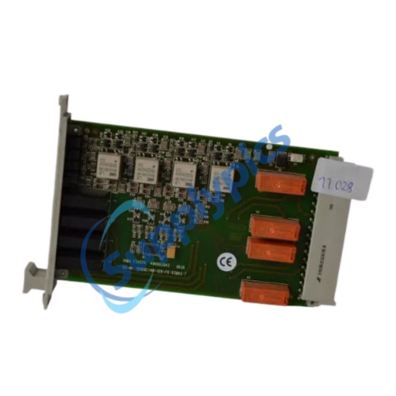
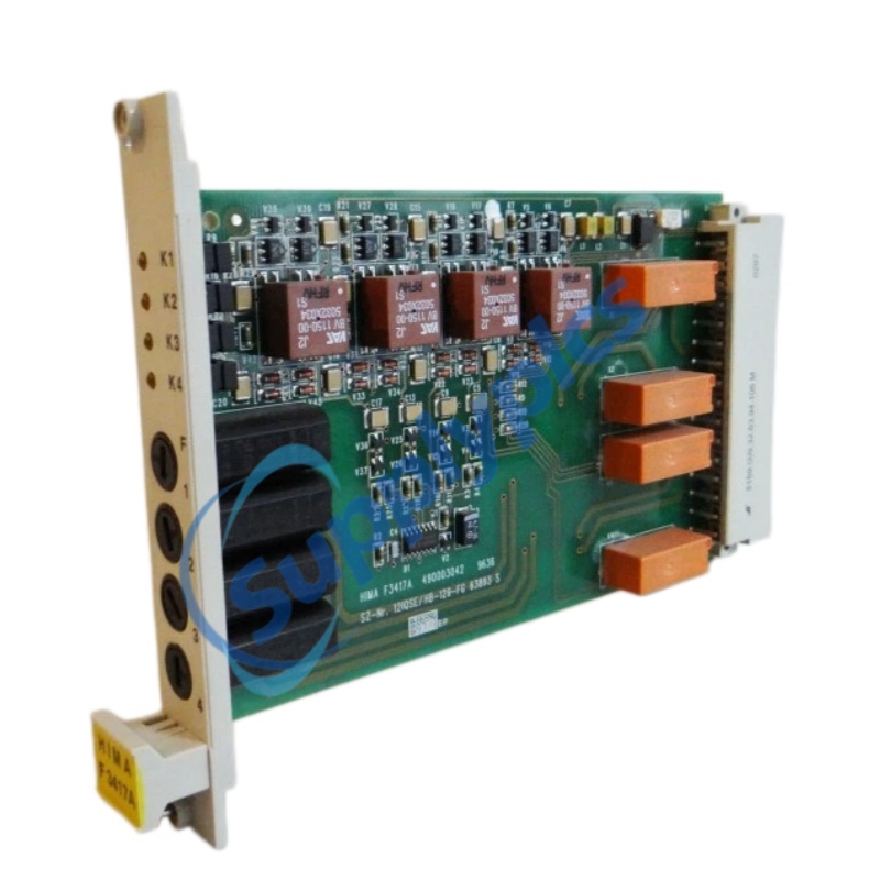
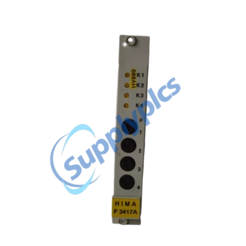
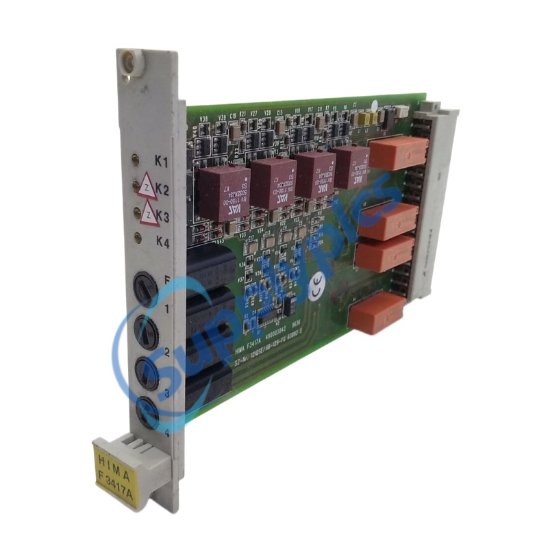
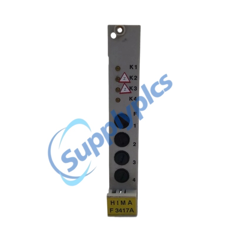
اسم المنتج: وحدة مُضاعِف ريلاي ذات ٤ قنوات
الاسم التجاري: HIMA
رقم الموديل: إف3417أ
بلد المنشأ: ألمانيا
الضمان: ١٢ شهرًا
واتساب: +٨٦ ١٨١٥٩٨٨٩٩٨٥
البريد الإلكتروني: [email protected]
الاسم التجاري: |
HIMA |
رقم الموديل: |
إف3417أ |
بلد المنشأ: |
ألمانيا |
تفاصيل التغليف: |
أصلي جديد مختوم من المصنع |
وقت التسليم: |
مدة التسليم: متوفر في المخزون |
شروط الدفع: |
تحويل بنكي |
القدرة الإنتاجية: |
متوفر في المخزون |
|
مدير المبيعات: |
ستيلا |
|
أرسل بريدًا إلكترونيًّا: |
|
|
التواصل عبر واتساب: |
|
المعلَّمة |
المواصفات |
|
الطراز |
F3417A (ويُشار إليها أيضًا بـ 17.034 / 985210213) |
|
الشركة المصنعة |
هِيما (ألمانيا) |
|
نوع المنتج |
وحدة مُضاعِف ريلاي آمنة ضد الأعطال ذات ٤ قنوات / وحدة معالجة اتصالات تعاونية |
|
توافق النظام |
HIMA H41q/H51q، بلانار F، HIMax |
|
قنوات |
٤ مخرجات ريلاي مستقلة من نوع SPDT |
|
جهد التغذية |
٢٤ فولت تيار مستمر (نطاق ١٢–٢٤ فولت تيار مستمر لبعض الإصدارات) |
|
تيار الإخراج (لكل قناة) |
حتى ٥ أمبير (٢٥٠ فولت تيار متردد / ٣٠ فولت تيار مستمر) |
|
أقصى تيار حمل (لبعض الإصدارات) |
١–٢ أمبير لكل قناة |
|
المعالج (النسخة الخاصة بالاتصالات) |
HD64180، ١٠ ميغاهيرتز |
|
الاتصالات (النسخة الخاصة بالاتصالات) |
منفذان RS485 (بسرعة تصل إلى ٥٧٦٠٠ بت في الثانية) |
|
بطارية احتياطية |
نعم (مُراقب) |
|
جهاز مراقبة السلامة |
نعم |
|
زمن الاستجابة |
≤20 مللي ثانية |
|
عزل |
≥٢,٥ كيلوفولت تيار مستمر (بين القناة والمنظومة) |
|
مستوى سلامة التكامل |
SIL 3 / AK 6–7 / الفئة ٤ (معتمد وفق معيار IEC 61508) |
|
درجة حرارة التشغيل |
من –25°م إلى +70°م |
|
نطاق درجة حرارة التخزين |
–40°C إلى +85°C |
|
فئة الحماية |
IP20 (للتركيب داخل خزانة) |
|
التثبيت |
سكة تثبيت DIN أو رف ١٩ بوصة (وحدة ارتفاع ٦U يوروكارد، عرض ٤ TE) |
|
الوزن |
تقريبًا ٠٫٢–٠٫٥ كجم (حسب النموذج) |
|
الشهادات |
توف، سي إي، يو إل |
|
حالة دورة الحياة |
منتهي الصلاحية (استُبدِلَ بـ F8627/F8626) |
الوحدة إف3417أ هو مُضخِّم ريلاي آمن متعدد القنوات (٤ قنوات) من شركة هايما، صُمِّم لتعزيز إشارات المنطق ذات القدرة المنخفضة القادمة من وحدات التحكم الآلي الآمنة إلى إشارات تبديل عالية القدرة تكفي لتشغيل الملفات اللولبية والمشغِّلات وصمامات الإيقاف الطارئ. إن إف3417أ يوفِّر أربعة مخرجات ريلاي مستقلة من النوع SPDT مع عزل لكل قناة، ويدعم أحمالًا تصل إلى ٥ أمبير عند ٢٥٠ فولت تيار متناوب أو ٣٠ فولت تيار مباشر. إن إف3417أ يعمل إما كوحدة مستقلة من نوع Planar F مثبتة على سكة دين، أو كوحدة معالجة اتصالات تعاونية ضمن نظام الرف ١٩ بوصة من طراز H41q، ويضم واجهتي RS485، ومرقِّب أمان، وشهادة SIL 3. إن إف3417أ يتبنّى تصميمًا آمنًا ضد الأعطال يُجبِر جميع الريلايات على الانتقال إلى حالة آمنة غير مشحونة عند انقطاع التغذية أو اكتشاف عطل داخلي.
هيكل عتادي آمن ضد الأعطال – عند انقطاع التغذية الكهربائية أو حدوث عطل داخلي أو فقدان إشارة الإدخال، تُجبر جميع الريلايات تلقائيًّا على الانتقال إلى حالة آمنة غير مشحونة، مما يضمن إيقاف المحركات الخطرة ويحقّق متطلبات تصميم أنظمة الإيقاف الطارئ للسلامة.
عزل مستقل لقناة رباعية – أربع قنوات ريلاية مستقلة تمامًا مع عزل كهربائي منفصل لكل قناة (≥٢٫٥ كيلوفولت تيار مستمر)، ما يضمن أن أي دائرة قصيرة أو عطل في ملف لفّ إحدى القنوات لا يؤثر على الدوائر الثلاث الأخرى لأنظمة القفل الآمن.
سعة تيار خرج عالية – تدعم كل قناة تيارًا يصل إلى ٥ أمبير عند ٢٥٠ فولت تيار متناوب أو ٣٠ فولت تيار مستمر، مما يتجاوز القيود المفروضة على بطاقات الإخراج الرقمي القياسية (مثل F3330/F3322 بسعة ٥٠٠ ملي أمبير وF3349 بسعة ٢ أمبير) عند تشغيل المحركات الثقيلة.
تكامل النظام المرنة – متوفر بعدة أشكال هندسية (ثابت على سكة DIN نموذج F، وحدة راك ١٩ بوصة نموذج H41q، ونظام HIMax) لتلبية مختلف متطلبات التركيب.
اعتماد سلامة مثبت عمليًّا – معتمد من TÜV لمستوى السلامة SIL ٣ / مستوى الأداء AK ٦–٧ / الفئة ٤ وفق معيار IEC 61508، وهو مناسب لأنظمة الأدوات السلبية الأكثر تطلبًا.
أربع قنوات ريلاية آمنة مستقلة – أربعة مخرجات ريلاي من النوع SPDT، وكل منها معزول كهربائيًّا بشكل مستقل
سعة إنتاج عالية – تصل إلى ٥ أمبير لكل قناة عند ٢٥٠ فولت تيار متناوب / ٣٠ فولت تيار مباشر، وهي مناسبة لتشغيل الأحمال التيار المتناوب الثقيلة مباشرةً
تصميم فشل-آمن – تنقطع جميع الريلايات عند انقطاع التغذية الكهربائية أو فقدان إشارة الإدخال أو اكتشاف عطل داخلي
تشخيص ذاتي لكل قناة – دائرتان لمراقبة كل ملف لف الريلاي للتحقق من حالة التلامس وكشف انقطاع سلك الملف أو التصاق التلامس
أنماط تشغيل قابلة للتخصيص – يمكن ضبط كل قناة بشكل مستقل على وضع التشغيل الآمن عند الفشل أو وضع التشغيل غير الآمن عند الفشل
قدرة وحدة المعالجة التعاونية للاتصالات – وحدة معالجة مركزية HD64180 بتردد ١٠ ميغاهيرتز، ومنفذان RS485 (بسرعة تصل إلى ٥٧٦٠٠ بت في الثانية)، وتواصل عبر ذاكرة RAM ذات المنفذين مع الوحدة المركزية
جهاز مراقبة السلامة ومراقبة الطاقة – مؤقت مراقبة مستقل ورصد لجهد النظام البالغ ٥ فولت
بطارية احتياطية – ساعة زمنية فعلية مدعومة بالبطارية مع رصد حالة البطارية
مؤشرات التشخيص الضوئية – مؤشرات حالة الطاقة/الخطأ/التشغيل لكل قناة
مخرج إنذار اللوحة – يمكن إدخال إشارة العطل إلى وحدة التحكم المنطقية الآمنة (PLC) لربط التشغيل الآلي
التثبيت – تركيب وحدة F3417A على سكة دين قياسية (النوع المستوي F) أو داخل خزانة مقاس ١٩ بوصة (مقاس ٦ وحدات أوروبية، عرض ٤ TE) حسب تكوين النظام.
مصدر الطاقة – توصيل تيار مستمر ٢٤ فولت (المدى المسموح به لبعض الأنواع: ١٢–٢٤ فولت تيار مستمر) إلى طرفي التغذية المخصَّصين. ويجب أن يكون مصدر التغذية ضمن مدى الجهد المحدد.
مخارج الإدخال – توصيل إشارات المنطق من وحدة المعالجة المركزية الآمنة ذات القدرة المنخفضة إلى مدخلات الوحدة. وتقوم الوحدة بتضخيم هذه الإشارات لتشغيل الأحمال الخارجية.
ومخرجات اتصال – توصيل أجهزة الحقل (مثل الصمامات الكهرومغناطيسية والمشغلات والريلايات والصمامات) بأطراف مخرج الريلاي ثنائي الاتجاه (SPDT). وتدعم كل قناة تيارًا أقصاه ٥ أمبير عند ٢٥٠ فولت تيار متردد أو ٣٠ فولت تيار مستمر.
الارضاء – التأريض السليم ضروري لمنع الضوضاء الكهربائية وضمان التشغيل الآمن.
الأسلاك — اتّبع إرشادات التوصيلات الصادرة عن الشركة المصنِّعة لتجنُّب التلف وضمان الأداء السليم.
التبديل أثناء التشغيل — جهاز F3417A لا لا يدعم التبديل أثناء التشغيل. يجب إطفاء التيار الكهربائي قبل استبدال الوحدة.
البيئة — تأكَّد من تركيب الوحدة في بيئة تحقِّق نطاقات درجة الحرارة والرطوبة المحدَّدة.
السؤال ١: ما هي الوظيفة الأساسية لجهاز F3417A؟
الإجابة 1: تم تصميم إف3417أ جهاز مكبِّر ريلاي آمن متعدد القنوات (ذو ٤ قنوات) يحوِّل إشارات المنطق ذات القدرة المنخفضة القادمة من وحدة معالجة السلامة إلى إشارات تبديل عالية القدرة، وهي قادرة على تشغيل الملفات اللولبية والمحرِّكات والصمامات والأحمال الثقيلة الأخرى مباشرةً في أنظمة الأدوات المؤمَّنة.
السؤال ٢: ما أقصى تيار خرج لكل قناة؟
الإجابة ٢: تدعم كل قناة حتى 5 أ ٢ أمبير عند ٢٥٠ فولت تيار متناوب أو ٣٠ فولت تيار مستمر. وبعض الإصدارات مُصنَّفة بسعة ١–٢ أمبير لكل قناة. تحقَّق من السعة المخصصة لإصدارك المحدَّد.
السؤال ٣: ما الذي يحدث إذا انقطَع التيار عن الوحدة أو كشفت عطلًا داخليًّا؟
ج3: إف3417أ يستخدم تصميم فشل-آمن : عند فقدان الطاقة أو فقدان إشارة الإدخال أو اكتشاف عطل داخلي، تُجبر جميع الريلايات على الانتقال إلى حالة غير مشحونة (مفتوحة)، مما يضمن إيقاف المحركات الخطرة بشكل آمن.
السؤال ٤: ما شهادات السلامة التي حصلت عليها وحدة F3417A؟
ج4: رأس إف3417أ معتمدة من TÜV وفقًا لـ المستوى SIL ٣ / التصنيف AK ٦–٧ / الفئة ٤ وفق معيار IEC 61508، ما يجعلها مناسبة لأنظمة الأدوات الآلية للسلامة (SIS) الأكثر تطلبًا.
السؤال ٥: هل لا تزال وحدة F3417A قيد الإنتاج؟
الجواب ٥: كلا. تم إيقاف إف3417أ هو منتهي الصلاحية منتج منتهي. وقد استُبدلت بوحدات أحدث مثل F8627 (إيثرنت) و F8626 (بروفيبوس-دي بي). تظل وحدات المخزون القديم الجديد (نوس) والوحدات المعاد تأهيلها متوفرةً للصيانة في الأنظمة القديمة.
 EN
EN