 EN

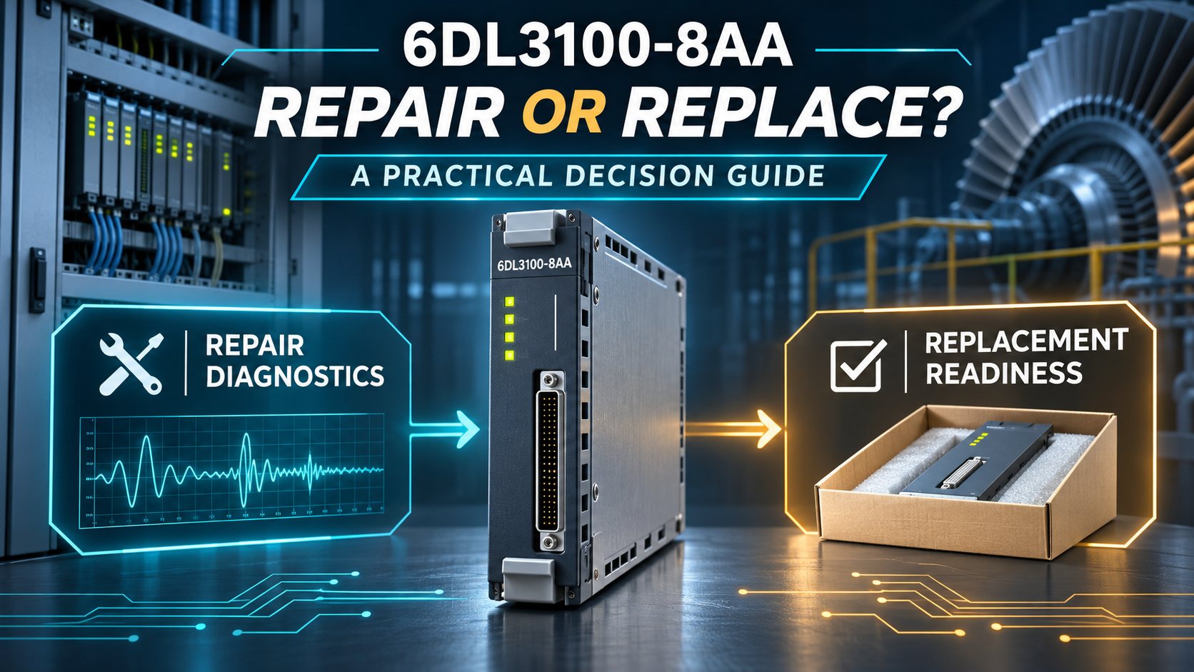
Communication alarms, unstable signals and startup faults do not always mean immediate replacement. The right decision depends on failure scope, revision, configuration, downtime risk and the condition of the available spare.
Use this guide to separate field-side issues from module faults, identify realistic repair candidates and prepare a controlled replacement when recovery time matters most.
What Is the Siemens 6DL3100-8AA?
The 6DL3100-8AA is an AddFEM Front End Module developed for demanding control applications, including high-speed turbine control. It provides process I/O handling, rapid signal acquisition and PROFIBUS DP communication for compatible automation systems.
- 24 V DC power supply using safely isolated PELV or SELV power.
- Analog inputs and outputs for process signals.
- Digital inputs and configurable digital I/O channels.
- High-speed counter inputs for rotational-speed measurement.
- Front-panel status and fault indication.
- DIN-rail or direct wall mounting inside a suitable cabinet.
For two-channel speed monitoring with rotational-direction detection, version 8 or later of the 6DL3100-8AA is required. Revision identification is therefore a key part of every repair or replacement decision.
Check the System Before Condemning the Module
A fault indication does not automatically prove that the AddFEM hardware has failed. Power quality, field wiring, grounding, connected transmitters and PROFIBUS communication can create similar symptoms.
Before removing the module, record the complete model, revision, serial number, PROFIBUS address, key-switch position, active LEDs, channel assignments and control-system diagnostic messages. Verify the 24 V DC supply under load and inspect connectors, shields and process wiring. Mixed current and voltage inputs also require the correct ground reference to prevent compensating currents and measurement errors.
When Repair Is the Better Choice
Repair is usually reasonable when:
- The fault is localized to a power, communication, connector or limited component-level problem.
- The original module has a known history and the correct revision for the installed application.
- An exact, traceable replacement is not immediately available.
- Planned downtime or redundant operation allows time for workshop testing.
- The repair facility can test power, PROFIBUS, analog I/O, digital I/O and counter functions.
A repaired module should not be accepted on the basis of a simple power-on test. It should be operated under realistic communication and I/O conditions, with the test results linked to its serial number. Faulty AddFEM hardware is not intended for component-level repair inside the plant cabinet; it should be evaluated in a properly equipped facility.
When Replacement Is the Safer Choice
Replacement is generally preferable when:
- The PCB has burned areas, severe corrosion, liquid contamination or damaged multilayer tracks.
- The processor, programmable devices or several isolated I/O sections are affected.
- The same module has failed repeatedly after previous repair.
- The installed revision does not support the required speed-monitoring function.
- A verified replacement can restore production faster than a repair cycle.
- The original module has an uncertain repair history or unreadable identification.
Do not assume that a 6DL3100-8AB or 6DL3100-8AC is automatically interchangeable with the 6DL3100-8AA. Later AddFEM versions introduce different communication, redundancy and diagnostic capabilities. The host configuration, GSD file, revision, I/O mapping and application requirements must be checked before substitution.
Repair or Replace: Quick Decision Guide
| Decision Factor | Repair | Replace |
|---|---|---|
| Fault scope | Localized and repeatable | Multiple circuits or major PCB damage |
| Revision | Correct installed revision | Revision unsuitable for the duty |
| Downtime | Planned outage available | Immediate recovery required |
| History | Original unit is traceable | Repeated failures or unknown history |
| Testing | Complete functional testing is available | Repair cannot be fully validated |
Replacement Preparation Checklist
Before ordering or installing a replacement, confirm:
- Complete model number and module revision.
- Serial number and clear nameplate photographs.
- PROFIBUS DP address and existing GSD configuration.
- Analog, digital and counter-channel assignments.
- Redundancy arrangement, if used.
- Condition of connectors, process cables and fiber-optic links.
- Required functional test report and delivery time.
The AddFEM process-wiring and power connector set is identified as 6DL9900-8AA. Existing connectors should be inspected for heat damage, corrosion, loose terminals and mechanical wear before reuse.
Testing After Repair or Replacement
After installation, verify power-up, PROFIBUS communication, analog signals, digital I/O, counter channels and front-panel indications. Compare live values with known process conditions before enabling automatic control. In a redundant arrangement, follow the documented master/reserve changeover procedure and avoid reconnecting the redundancy link in a way that may cause unintended switching.
Frequently Asked Questions
Component-level repair should not be carried out inside the operating cabinet. The module should be removed safely and tested in an equipped repair facility.
Not automatically. Configuration, revision, communication behavior, I/O mapping and application requirements must be verified first.
Some functions depend on the hardware or firmware revision. Rotational-direction detection requires version 8 or later.
Provide the full model, revision, label photographs, fault description, application, delivery requirement and requested test documentation.
Technical Reference
Recommended Products
| DSP-2 v2 ,EN54-16 ,F01U101303 | EASY400-P0W | T15HD 60-798-02 |
| Tx0D 3020 0JF737 4GF/2GR | L4E 638-662 | DVR1 [0413] |
| TXM1.8X | 7101/IP1P E100 | 4269-462.04 |
| DM-DA4-4K-C | EKA173/5 | 779153-001 |
| KFA6-SR2-EX2.W 103373S | CRD5107HPB | 950-0487 MSU-3 R90550 MSU3 |
| MU-KDPR05 /51201397-005 | MH3471BLKC | TM3DQ16RG |
| KFD2-STC4-120 | EL5401D8011 | 573912 |
| EXPI-4 | XFL 523 | G2PF400VS02 |
| ABB 2CDG 120 039 R0011 | 3/209 GHG137 | FLM-420-O1I |
| MTN649310 REG-KNX /230/1000W | SE-KP2N | SKA1200037 |
| ET12 | 9857333 | 7P016XL |
| DIN-MSR-05-04 | CS540 | 2CDG110080R0011 |
| METSEDM6000HCL10NC DM6000H | 20-0268-40 | GT1155-QSBD GOT1000 |
Contact Us
Table of Contents
- What Is the Siemens 6DL3100-8AA?
- Check the System Before Condemning the Module
- When Repair Is the Better Choice
- When Replacement Is the Safer Choice
- Repair or Replace: Quick Decision Guide
- Replacement Preparation Checklist
- Testing After Repair or Replacement
- Frequently Asked Questions
- Technical Reference
- Recommended Products
- Contact Us