
Overview of the Function of 1771-ASB
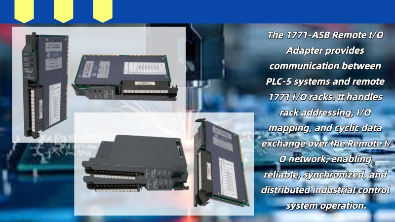
The 1771-ASB (Remote I/O Adapter) is a rack-level communication adapter module in the PLC-5 Remote I/O system. It connects the 1771 I/O rack to the Remote I/O network and facilitates data exchange with the master PLC. It does not directly process field signals; instead, it handles communication, address mapping, and data synchronization for the remote I/O rack, enabling the PLC to access remote devices through a unified I/O address.
Its main functions include:
Responsible for remote I/O communication, enabling data upload and download between the rack and PLC.
Configuring rack addresses and rack structures via DIP switches to achieve I/O image area mapping.
Updateing data according to the PLC scan cycle to ensure real-time remote I/O.
Providing basic status indication and communication fault diagnosis functions.
Supporting distributed I/O architecture expansion, reducing the complexity of long-distance cabling.
The Core Function of DIP Switches
DIP switches are the primary configuration method for local hardware configuration of the 1771-ASB, used to directly define the operating parameters of the remote I/O rack without the involvement of host computer software. Through these switches, the module can determine its identity and data organization method in the Remote I/O network, thus immediately participating in PLC communication according to predetermined rules after power-on. Its configuration result is "hardware as system parameters," and once set, it determines the behavior of the remote rack in the entire PLC-5 I/O system, therefore playing a fundamental and irreplaceable role in field applications.
Rack Address Setting Rules
The Rack Address is a unique identifier for each 1771-ASB remote I/O rack, serving as the core basis for the PLC to distinguish different remote sites. This address is set using DIP switches in a binary weighted manner, with different switches corresponding to different weights (e.g., 1, 2, 4, 8, 16, 32). The final address value is obtained through ON/OFF combinations. Each rack address must be unique; otherwise, the PLC will be unable to correctly distinguish the data source during scanning, leading to I/O data corruption or even overwriting. In actual engineering, it is usually planned in conjunction with equipment partitioning or process units to ensure logical addressing, facilitating later maintenance, expansion, and fault location, while also contributing to a clear organization of the PLC scanning structure.
Rack Size Setting
Rack Size defines the size of the data structure occupied by the remote I/O rack in the PLC I/O image area. It directly determines the organization method and scanning granularity of I/O data. Common architectures in the 1771 system include 1/4 Rack, 1/2 Rack, and Full Rack, each corresponding to a different number of I/O group mappings. If the Rack Size is set too large or too small, and the PLC configuration is inconsistent, it will lead to input/output data misalignment. For example, some input points may display abnormal changes in the PLC, or some modules may not be recognized at all. Since the PLC-5 Remote I/O operates based on a fixed image area mechanism, correct Rack Size matching is a prerequisite for stable system operation. During field debugging, it is usually necessary to verify the Rack Size against the PLC program configuration one by one.
I/O Address Mapping Logic
I/O address mapping is the core mechanism for data interaction between the 1771-ASB and the PLC. Essentially, it converts the data from the field physical I/O modules into a logical address space that the PLC can directly access. In a PLC-5 system, remote I/O typically exists in the form of I:x.y and O:x.y, where x represents the rack address and y represents the group or slot number within the rack. The 1771-ASB will package the data from all I/O modules within the rack according to the PLC's scan cycle and map it to the PLC's input/output image area, thus realizing the conversion from physical signals to logical addresses.
To understand this more intuitively, it can be viewed as a "hierarchical mapping relationship," as shown in the table below:
| Physical Structure (Field Rack) | PLC Logical Address | Description |
| Rack 0 Input Module Group 0 | I:0.0 | Input data group 0 of Rack 0 |
| Rack 0 Output Module Group 1 | O:0.1 | Output data group 1 of Rack 0 |
| Rack 3 Input Module Group 2 | I:3.2 | Input data group 2 of Rack 3 |
| Rack 10 Output Module Group 0 | O:10.0 | Output data group 0 of Rack 10 |
This mechanism operates using a periodic scanning method, rather than real-time event triggering. Therefore, there is a fixed scan cycle delay between the PLC and the remote I/O. The 1771-ASB completes input data acquisition, packet uploading, and output data reception and distribution within each scan cycle, enabling the system to maintain a simple structure while possessing strong determinism and stability. This is one of the important reasons why Remote I/O can be used in industrial fields for a long time.
Common Configuration Errors and Problems
In field applications, most problems with the 1771-ASB stem from inconsistencies in basic configurations. The most common is duplicate Rack Address settings, which prevents the PLC from distinguishing data sources from different racks during scanning, leading to input/output confusion or signal overlap. Secondly, incorrect Rack Size configuration is a frequent issue. When the ASB setting doesn't match the PLC's configuration, it causes I/O data mapping offsets, resulting in some input points logically corresponding to incorrect physical signals. Furthermore, incorrect DIP switch direction determination is another high-frequency problem. Since different batches of modules may have different ON/OFF directions, reversing the settings is easily caused if the manual isn't consulted in the field. Finally, modifying DIP configurations while the circuit is powered on can lead to abnormal module status or even communication failure; therefore, the principle of power-off operation must be strictly followed.
Debugging Recommendations (Field Experience)
During actual debugging, it is recommended to start with the most basic hardware configuration rather than directly checking the PLC program. First, the DIP switch settings should be completed while the power is off, ensuring the Rack Address is unique and non-conflicting. Second, verify that the Rack Size is completely consistent with the PLC-side Remote I/O configuration. After powering on, observe the status indicator lights on the 1771-ASB panel. The ACTIVE and FAULT statuses can provide a preliminary indication of whether communication has been established. If communication is normal but data is abnormal, focus on checking whether the I/O mapping area corresponds correctly and observe whether the input and output in the PLC monitoring interface are updated synchronously with changes in the field. Experience shows that most problems are concentrated in the address and structure configuration stage, rather than failures in the communication hardware itself.
Summary
All the core functions of the 1771-ASB revolve around DIP switch configuration, which essentially defines the identity and data structure of the remote I/O rack in the PLC network through hardware. The Rack Address determines "who" the rack is, the Rack Size determines "how" the rack organizes data, and the I/O mapping logic determines "how" the PLC reads this data. All three elements must be consistent and logically correct to ensure the stable operation of the Remote I/O system. In the PLC-5 architecture, this deterministic mechanism based on hardware configuration enables the system to maintain reliability and consistency over a long period, even in complex industrial environments.