Home > Products > SIEMENS > SIMATIC S7 Series
|
Outputs
8 digital outputs |
Output type
24 V DC, P-switching |
Rated current
0.75 A per output |
ARTICLE NUMBER
6ES7288-2DT08-0AA0
|
PRODUCT TYPE
SM DT08, DQ 8x24 V DC/0.75 A
|
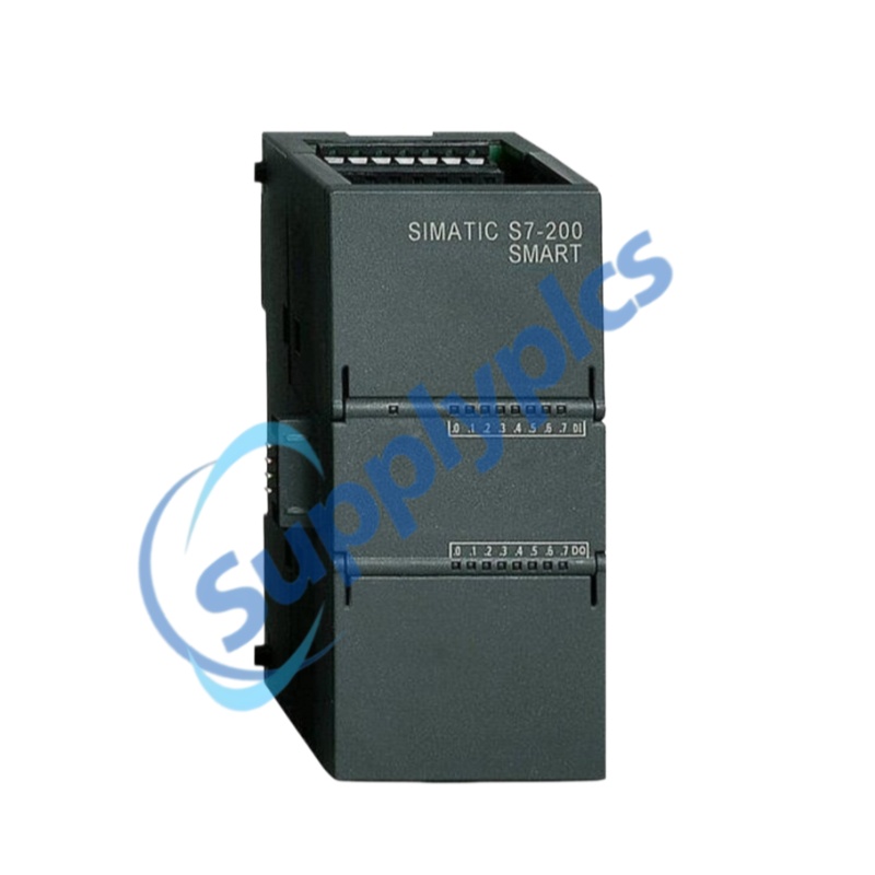
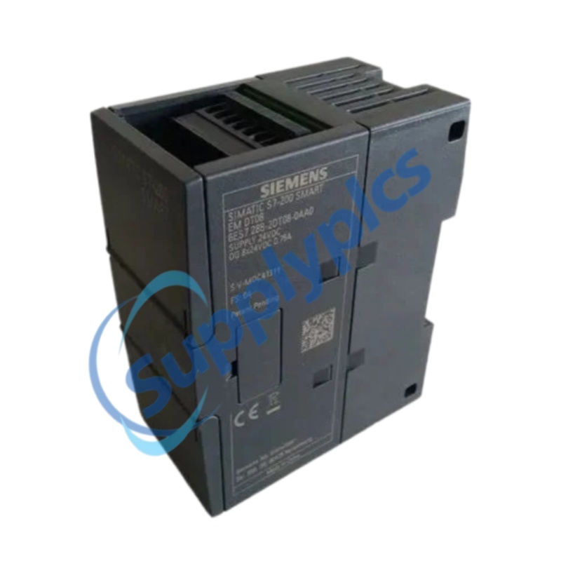
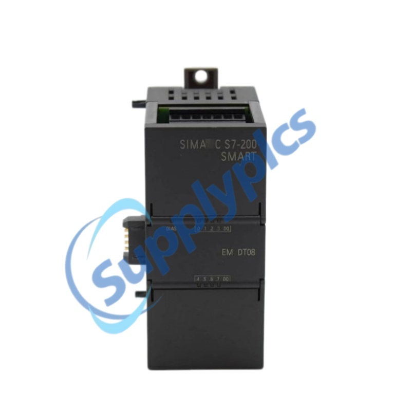
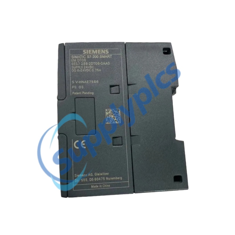
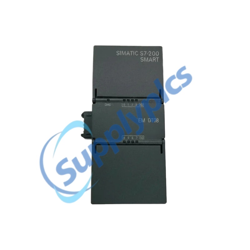
The Siemens SIMATIC S7-200 SMART SM DT08 is a digital output signal module identified by article number 6ES7288-2DT08-0AA0. The official product description specifies eight 24 V DC transistor outputs rated at 0.75 A each.
Core selling point: Eight 24 V DC P-switching transistor outputs rated at 0.75 A each.
|
OUTPUT EXPANSION
Eight transistor channels arranged in two groups.
|
|
|
Rated supply voltage
|
24 V DC; permissible range 20.4 V DC to 28.8 V DC.
|
|
Digital outputs
|
8 transistor outputs in 2 groups; P-switching, current-sourcing.
|
|
Output current
|
0.75 A rated per output; 3 A maximum total current per output group under the specified operating conditions.
|
|
Output voltage
|
Signal 1: minimum 20 V DC; signal 0: maximum 0.1 V.
|
|
Residual current
|
Maximum 10 µA at signal 0.
|
|
Output delay
|
Maximum 50 µs from 0 to 1; maximum 200 µs from 1 to 0 for resistive load.
|
|
Permissible load
|
Maximum 0.75 A resistive load; maximum 5 W lamp load.
|
|
Cable length
|
Maximum 500 m shielded; maximum 150 m unshielded.
|
|
Dimensions and weight
|
45 mm × 100 mm × 81 mm; approximately 147 g.
|
|
Terminal block X10
|
Terminal block X11
|
|
Channel indication
Output-status diagnostic LEDs are provided for the digital output channels. |
Channel isolation
Channels are isolated via optocouplers; the official data lists a 500 V AC, 1 minute isolation test. |
|
ENCLOSURE
IP20
|
SHORT-CIRCUIT PROTECTION
Not provided
|
CONFORMITY
CE listed
|
|
1 · Architecture
|
Confirm the exact S7-200 SMART CPU, expansion architecture, module count and applicable firmware/manual revision.
|
|
2 · Electrical
|
Confirm 24 V DC supply quality, P-switching load compatibility, inrush current, group-current limit and switching rate.
|
|
3 · Protection
|
Because short-circuit protection is not provided, define suitable external protection and safe isolation for the application.
|
|
4 · Wiring
|
Use the official X10/X11 terminal assignment; verify conductor selection, polarity, functional earth and cable length.
|
|
Article identity
|
Match 6ES7288-2DT08-0AA0 on the quotation, module label and available documentation.
|
|
System fit
|
Confirm S7-200 SMART CPU compatibility, permitted expansion position and module capacity.
|
|
Output topology
|
Verify that eight 24 V DC P-switching transistor outputs meet the circuit design.
|
|
Load schedule
|
Check steady-state current, inrush current, lamp load, switching rate and inductive-load suppression.
|
|
Group current
|
Verify the 3 A maximum per output group against temperature and mounting conditions.
|
|
Protection
|
Define external overcurrent and short-circuit protection because it is not integrated.
|
|
Documentation
|
Request the applicable datasheet, declarations and manual revision when required.
|
|
Commercial evidence
|
Confirm condition, stock status, current photos, testing, warranty, dispatch and payment terms before order.
|
|
Physical stock
|
Confirm before quotation. No quantity claim is made without current warehouse evidence.
|
|
Condition
|
New, used or refurbished status is subject to verification for the offered unit.
|
|
Current photos
|
Current physical-product and nameplate photos are available on request, subject to availability.
|
|
Warranty
|
Confirm the warranty period and coverage before quotation.
|
|
Dispatch time
|
Subject to verification after stock, inspection and destination are confirmed.
|
|
Testing
|
Testing status and any available test record are available on request; do not assume a test has been completed.
|
|
Payment methods
|
Accepted methods will be stated in the pro forma invoice; confirm before quotation.
|
|
Quotation response
|
Subject to verification based on the requested quantity, destination and documentation scope.
|
|
Transaction confidence
|
Company documents, payee details and the transaction process are available on request. Verify beneficiary and order details before payment.
|
|
Cross-reference selection: The following model references are provided for enquiry planning. Confirm the complete part number, manufacturer, revision and application before quotation.
|
|
04079115-k5
|
AVM102P
|
MCP250M
|
RLU220
|
Z031.408
|
|
SA-S-T1
|
FMI-100C5
|
51196989-100/124662-1
|
1C31161G02
|
SB401-10-S1
|
|
SPD910-1000PA
|
HE500TIU112A-311
|
S56CB4N
|
3HE05894AAAA01
|
S500A-V5.0
|
|
WV-U2530L
|
RA92-00644A
|
68-4003-06
|
50098566
|
1771-IBN
|
|
HLS-SE20J
|
Dec-00
|
6ES7972-0BA52-0XA0
|
SO816N.A001
|
LC1D09N7
|
|
BAS34U24V
|
MTN683832
|
PXC36.1-ED
|
MTN680204
|
EHS-220
|
|
IOEXP-C02B
|
AIR-ANT2413P2M-N
|
CR1021-04
|
EPM-34
|
UN2-DI4-00
|
|
RSM32F
|
1399.19.0024
|
SFA-S2
|
248RANA
|
4819919
|
|
DIN-MSR-05-04
|
6ES7326-1BK01-0AB0
|
SISTF1011-111-LRT
|
FGV-100XY
|
KTXL-116G-16
|
|
20-0635-30
|
MTK15-485
|
KFD0-CS-EX1.56
|
TSP70
|
KFD2-SOT2-EX1.LB
|
|
Selection note: Availability, condition, testing, warranty and dispatch are subject to verification. Request the current quotation and supporting product evidence before ordering.
|
 EN
EN