|
BENTLY NEVADA | 3300 XL 8 MM
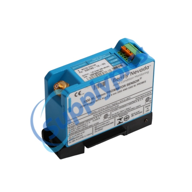
330180-12-05
3300 XL Proximitor Sensor
1.0 m probe-only system | No mounting hardware | CSA, ATEX and IECEx approvals
|

Bently Nevada 330180-12-05
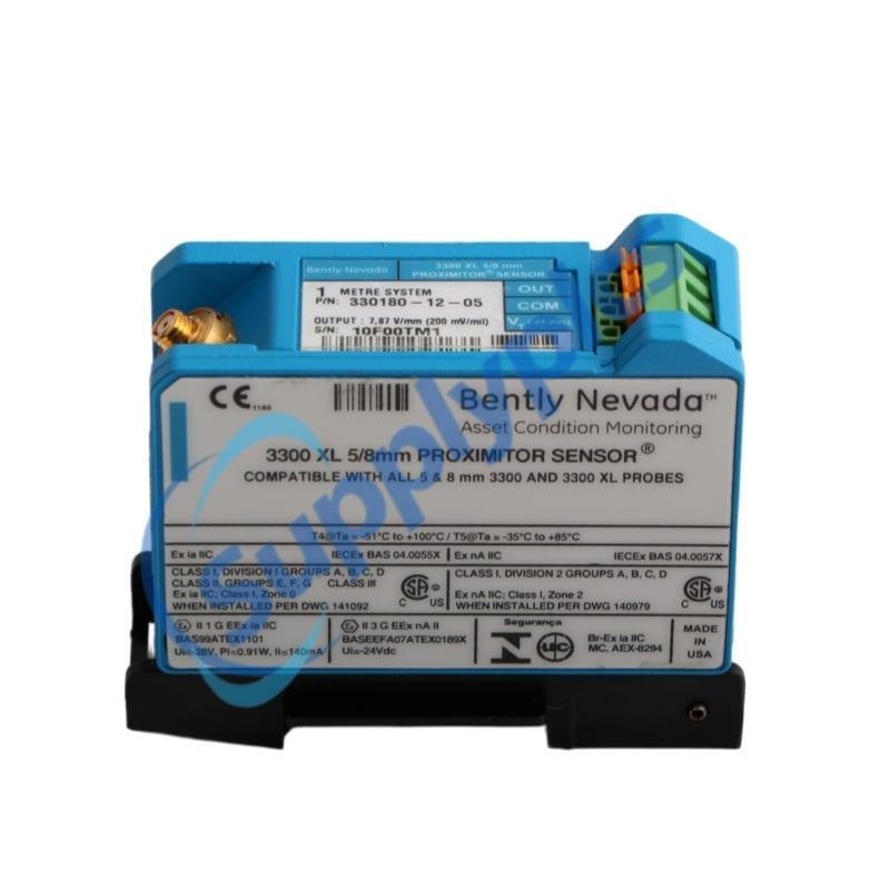
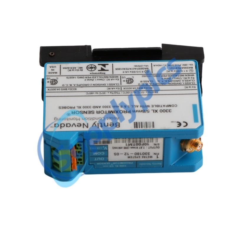
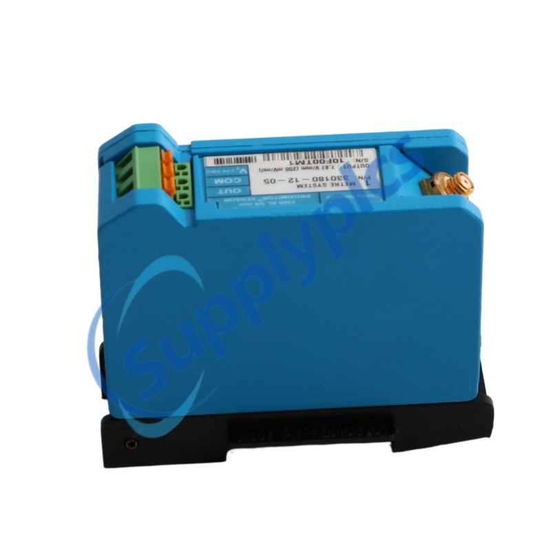
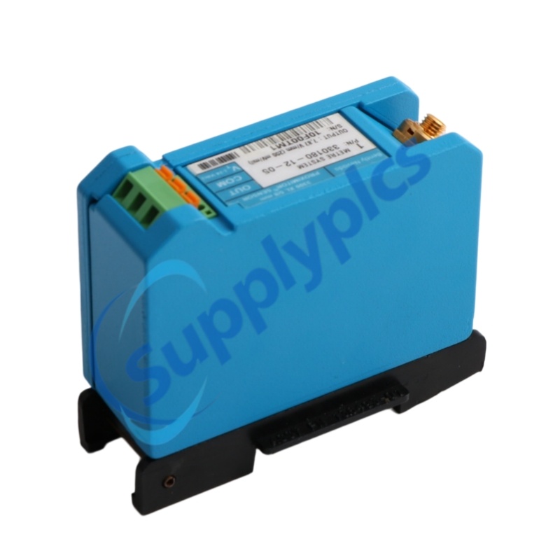
The 330180-12-05 is a 3300 XL Proximitor Sensor configured for a 1.0 meter probe-only system. Ordering option 12 specifies no mounting hardware, while option 05 specifies CSA, ATEX and IECEx approvals. It accepts a non-contacting 3300-series 5 mm or 3300 XL 8 mm proximity probe and provides an output proportional to the distance between the probe tip and the observed conductive surface.
Core value: compact 1.0 m probe-only signal-conditioning configuration with multi-agency hazardous-area approvals.
|
|
OFFICIAL SPECIFICATIONS | 330180-12-05
|
|
|
Complete model
|
330180-12-05
|
|
Product family
|
3300 XL 8 mm Proximity Transducer System
|
|
Product type
|
3300 XL Proximitor Sensor
|
|
Dimensions
|
Sensor housing shown: 50.8 x 50.8 x 63.5 mm (2.00 x 2.00 x 2.50 in); supplied without mounting hardware
|
|
Weight
|
246 g (8.67 oz)
|
|
Ordering option 12
|
1.0 m (3.3 ft) system length, no mounting hardware
|
|
Agency approval option 05
|
CSA, ATEX and IECEx approvals
|
|
System configuration
|
1.0 m probe-only system; no extension cable
|
|
Accepted probe input
|
One non-contacting 3300-series 5 mm or 3300 XL 8 mm proximity probe
|
|
Supply voltage
|
-17.5 to -26 Vdc for non-incendive installation; -23 to -26 Vdc with barriers
|
|
Current consumption
|
12 mA maximum
|
|
Output resistance
|
50 ohm
|
|
Linear range
|
2.0 mm (80 mils), approximately 0.25 to 2.3 mm from target
|
|
Recommended radial gap
|
-9 Vdc, approximately 1.27 mm (50 mils)
|
|
Incremental scale factor
|
7.87 V/mm (200 mV/mil) +/-5% for standard 1 m system at 0 to +45 C
|
|
Deviation from best-fit line
|
Less than +/-0.025 mm (+/-1 mil) for standard 1 m system at 0 to +45 C
|
|
Frequency response
|
0 to 10 kHz, +0/-3 dB
|
|
Field wiring
|
0.2 to 1.5 mm2 (16 to 24 AWG), 3-conductor shielded triad recommended
|
|
Maximum field wiring length
|
305 m (1,000 ft) between Proximitor Sensor and monitor
|
|
Sensor material
|
A308 aluminum
|
|
Probe connector
|
Corrosion-resistant gold-plated ClickLoc connector
|
|
Field terminals
|
SpringLoc terminal strips
|
|
Operating temperature
|
-52 to +100 C (-62 to +212 F)
|
|
Storage temperature
|
-52 to +105 C (-62 to +221 F)
|
|
Compliance
|
FCC Part 15; EMC 2014/30/EU; RoHS 2011/65/EU; SIL 2, HFT=0; SIL 3, HFT=1
|
|
CONTACT
STELLA
|
|
Radial vibration
Measures dynamic shaft vibration through the proportional proximity output. |
Axial position
Measures static shaft position within the 2.0 mm linear range. |
|
Keyphasor reference
Supports phase and speed reference measurements when applied within system guidance. |
Interchangeable platform
Compatible with 3300 XL 8 mm components and electrically and physically interchangeable with non-XL 3300 5 mm and 8 mm components, subject to system limits. |
|
Input
|
One non-contacting 3300-series 5 mm or 3300 XL 8 mm probe
|
|
Power
|
-17.5 to -26 Vdc; -23 to -26 Vdc with barriers
|
|
Maximum current
|
12 mA
|
|
Output resistance
|
50 ohm
|
|
Linear span
|
2.0 mm (80 mils)
|
|
Scale factor
|
7.87 V/mm (200 mV/mil) +/-5% for this 1 m system
|
|
Frequency response
|
0 to 10 kHz, +0/-3 dB
|
|
Field terminals
|
SpringLoc terminal strips
|
|
Field cable
|
3-conductor shielded triad, 0.2 to 1.5 mm2 recommended
|
|
1 | Confirm the exact configuration
Use a 1.0 m probe-only arrangement. No extension cable is used with this ordering option. |
|
2 | Provide the mounting method
Ordering code 12 supplies the Proximitor Sensor without mounting hardware; the installation must provide suitable support and required terminal protection. |
|
3 | Wire and gap correctly
Use the specified negative DC supply, shielded triad field wiring and the SpringLoc terminals. A radial vibration setup uses approximately -9 Vdc at 1.27 mm nominal gap. |
|
4 | Verify the complete loop
Confirm the probe type, target material, linear range and monitor input before commissioning. Factory calibration is for an AISI 4140 steel target unless otherwise ordered. |
|
Option 05
CSA, ATEX and IECEx approvals |
EMC and FCC
FCC Part 15; EMC Directive 2014/30/EU |
|
RoHS
RoHS Directive 2011/65/EU |
Functional safety
SIL 2 with HFT=0; SIL 3 with HFT=1 |
|
For hazardous-area use, installation must follow the applicable Bently Nevada drawing and protection method. The Proximitor terminals require at least IP54 protection for the specified ATEX/IECEx nA/ec installation.
|
|
|
Q1. How can a buyer verify that the quoted unit is the exact 330180-12-05?
A. Match the full nameplate part number, not only the 330180 base number. The middle code 12 must identify the 1.0 m probe-only system with no mounting hardware, and the final 05 must identify CSA, ATEX and IECEx approvals.
|
|
Q2. How can New, Used and Refurbished condition be distinguished for this Proximitor Sensor?
A. Request current photos of the housing, terminal strip, connector, nameplate and packaging. A new unit should show no wiring marks, tool marks, terminal wear, contamination or replaced labels; compare all visible codes with 330180-12-05.
|
|
Q3. How should procurement verify that the supplier is legitimate and reliable?
A. Check the legal company name, business registration, verifiable address, company-domain communication history, bank beneficiary consistency and written traceability for the exact 330180-12-05 before accepting commercial terms.
|
|
Q4. Which technical points should an engineer confirm before purchase?
A. Confirm the 1.0 m probe-only configuration, absence of an extension cable, no supplied mounting hardware, negative DC supply range, 12 mA maximum current, 2.0 mm linear range, 7.87 V/mm scale factor, 50 ohm output resistance and option 05 approval requirement.
|
|
Q5. What physical evidence should be requested before payment?
A. Ask for dated photos or video showing the complete 330180-12-05 nameplate, connector, SpringLoc terminals, housing condition, packaging labels and measurable dimensions. Where testing is offered, request the actual serial-numbered test record and output evidence.
|
|
Q6. Can a similar 330180 suffix replace 330180-12-05?
A. Not automatically. Codes 10 and 11 change the mounting provision, codes 50 through 92 change system length or mounting, and suffix 00 removes the option 05 approvals. Any substitute must be checked against the required 1.0 m probe-only configuration, mounting plan and hazardous-area approval basis.
|
|
60 INDUSTRIAL MODELS
|
||
|
ABB TU505 A3 1SAP21020099901
|
AMM-2F
|
TLS3-GD2
|
|
Xm30 X13651469010
|
1051 A004-9
|
NJS8477EN
|
|
DN15 TSMR-015-A5T-MB
|
S4-34805
|
PSR-SCP-24DC/ESP4/2X1/1X2
|
|
3RT2015-1BB41
|
AVPLY-R9300
|
96K-1070-43
|
|
51196989-100/124662-1
|
LTE-ANTM2-SMA-D
|
MTL5541
|
|
722/921 3953-5722 722/221CA/0
|
ES-240-24
|
ABB 3BSE020846R1 3BSE037760R1
|
|
STI-3150
|
ENCL-MZ800-PAN
|
APIN0305 IAP-305-RW
|
|
PQ3541
|
60-1471-12
|
6GK5212-2BB00-2AA3
|
|
600 L25 0,5
|
Legrand 03609
|
VS-ZP3102+.EU
|
|
TST8801
|
LV429032 3P3D TM63D
|
GLC100-FN11
|
|
EXP-2200 LBL-EXP2200
|
HWS600-24/LNT
|
CEAS410754-01-01 HK50AA004
|
|
II-7520 RS-232 RS-485
|
Alerton EXP-2200
|
RS900 RS900NC-48-D-00-00-L2-XX
|
|
6ES7422-1HH00-0AA0
|
AVPLY-R9200
|
1756-OW16I
|
|
PM582 1SAP140200R0201
|
SEGCM-EXT12D
|
2N 9151002
|
|
TP57AT/703049
|
DO561 / 1TNE968902R2201
|
MBT5560
|
|
60-998-01
|
MPPIO-T0258 MPPF9850
|
48503010
|
|
E1ZM10
|
DM-SCALER-C
|
Urmet 1071/7
|
|
3HE00868CBAA01
|
C2N-SSC-2 6500454
|
SX-300-TCP A700-1153
|
|
2CDG 110 063 R0011
|
ABB COM0037 3386040012 2RCA035919A0001
|
AQM2200
|
|
MPC-M25-W 6502449
|
40071343764
|
OLC100
|
 EN