Get a Free Quote

Our representative will contact you soon.
Email
Name
Mobile
Company Name
Message
0/1000
bently nevada 9200 9200 01 01 10 00 two wire seismoprobe velocity transducer original new-0

Bently Nevada Sensor

Home >  Products >  BENTLY NEVADA >  Bently Nevada Sensor

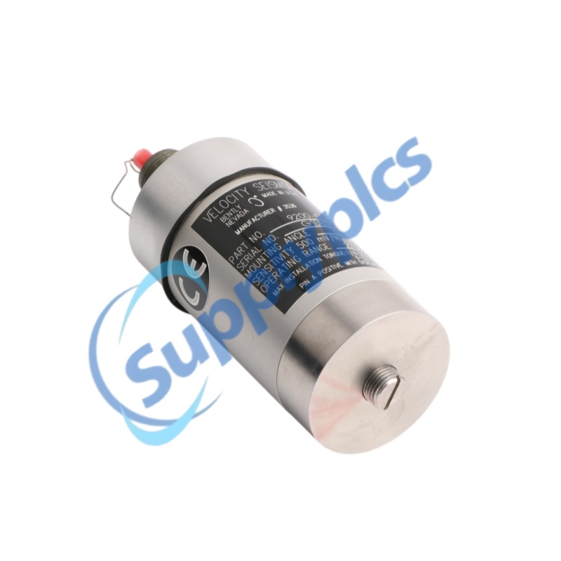
Bently Nevada 9200 9200-01-01-10-00 Two-Wire Seismoprobe Velocity Transducer | Original New

BENTLY NEVADA · 9200 SEISMOPROBE
9200-01-01-10-00
Two-Wire Moving-Coil Velocity Transducer
Frequency: 4.5 Hz to 1 kHz · Sensitivity: 20 mV/mm/s · Mounting: Top mount, no cable · Mounting: M10x1 circular base
Approval: No approvals
LEAD TIME: In stock    WARRANTY: 1 year
Appurtenance:
  • Overview
  • Technical Data
  • Inquiry
  • Applications
  • Construction
  • Installation
  • Compatibility
  • FAQ
  • Recommend Models
  • Recommended Products

OFFICIAL PRODUCT OVERVIEW
9200 two-wire velocity Seismoprobe
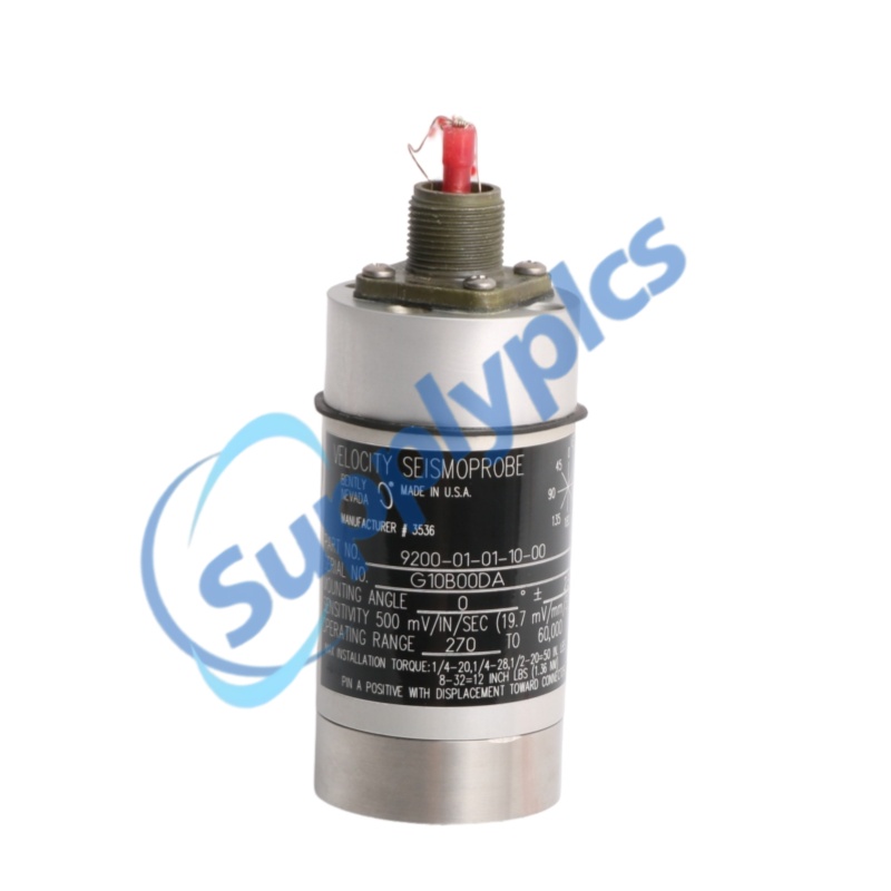
Bently Nevada 9200-01-01-10-00 is a self-powered two-wire moving-coil velocity transducer for bearing housing, casing and structural vibration measurements. The code specifies 0 degree orientation with 4.5 Hz minimum operating frequency, top-mount connector, circular M10x1 base and no agency approvals.
Core selection point: Direct velocity output without an external power supply.

Technical Data

VERIFIED SPECIFICATIONS
Official configuration data
Key dimensions, weight, construction and ordering-code details for this complete model.
Complete model
9200-01-01-10-00
Product family
Bently Nevada 9200 and 74712 Seismoprobe Velocity Transducers
Product type
Two-wire moving-coil velocity transducer
Dimensions
102 mm (4 in) typical height x 41 mm (1.6 in) typical diameter
Mounting dimension
Circular base with M10x1 stud, option 10
Weight
300 g (10.5 oz) typical
Mounting angle / minimum frequency
0° ±2.5°; 4.5 Hz (270 cpm), option 01
Frequency response
4.5 Hz to 1 kHz (270 to 60,000 cpm), +0 / -3 dB typical
Sensitivity
20 mV/mm/s (500 mV/in/s) ±5%
Calibration load
10 kΩ across pins A and B
Dynamic operating range
2.54 mm (0.100 in) peak-to-peak maximum displacement
Velocity range
25 mm/s (1 in/s) at 100 Hz under stated conditions
Coil resistance / inductance
1.25 kΩ ±5%; 125 mH typical
Operating and storage temperature
-29°C to +121°C (-20°F to +250°F)
Connector / approval
Top mount, no cable; option 00 no approvals

Inquiry

DIRECT CONTACT
STELLA
Fast access to the person handling product and quotation questions.

Applications

FIELD APPLICATIONS
Direct velocity measurement for rotating and structural assets
The 9200 Seismoprobe is a self-powered moving-coil transducer for measuring absolute vibration velocity on bearing housings, machine casings and structural locations. Its two-wire output supports permanent monitoring and diagnostic use without an external sensor power supply.
Continuous monitoring
Measures absolute vibration velocity on machinery housings and structures for connection to compatible protection or condition-monitoring channels.
Low-frequency response
Option 01 is calibrated for the 0 degree orientation and provides a 4.5 Hz lower operating frequency for applications that require response below typical high-speed machinery ranges.
Self-powered output
The moving-coil sensing element generates a direct two-wire velocity signal, simplifying field wiring while preserving polarity and load requirements.
Installation fit
The top connector and circular M10x1 mounting base support a compact permanent installation when the specified orientation, surface preparation and tightening practice are followed.

Construction

BUILD & CONNECTION
Construction and interfaces
Physical design, materials and connection points for this product.
Sensing element: Moving-coil velocity mechanism with direct output proportional to vibration velocity.
Electrical output: Two-wire output across pins A and B; no external power supply is required.
Connector: Top-mount connector without integral cable, option 01.
Mounting base: Circular base with M10x1 stud, option 10, for the specified 0 degree orientation.

Installation

FIELD PRACTICE
Installation checkpoints
Key steps for correct mechanical and electrical installation.
01
Mount the sensor at 0° within the specified ±2.5° calibration orientation.
02
Prepare a flat rigid mounting surface and tighten the M10x1 stud to the published torque.
03
Connect the two-wire top-mount cable and preserve pin A / pin B signal polarity.
04
Route shielded cable to the compatible monitor and account for frequency roll-off on long runs.
05
Verify that no agency approval is required because option 00 is specified.

Compatibility

SYSTEM FIT
Compatibility and selection checks
Confirm mechanical fit, signal path and ordering-code requirements.
Measurement use: Designed for absolute bearing-housing, machine-casing and structural velocity measurements.
Monitor connection: Maximum lead length is 305 m to compatible 3300 or 3500 monitoring inputs, subject to frequency response.
Mechanical fit: Requires the circular M10x1 mounting stud and the specified 0 degree orientation.
Approval: Option 00 indicates no agency approval; do not substitute an approved configuration without review.

FAQ

BUYER CHECKLIST
Six practical verification questions
Model-specific checks for engineering and procurement review.
Q1. How can a buyer verify the exact transducer configuration?
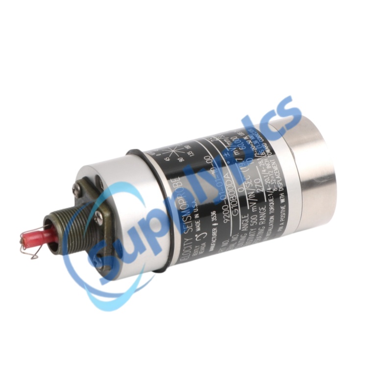
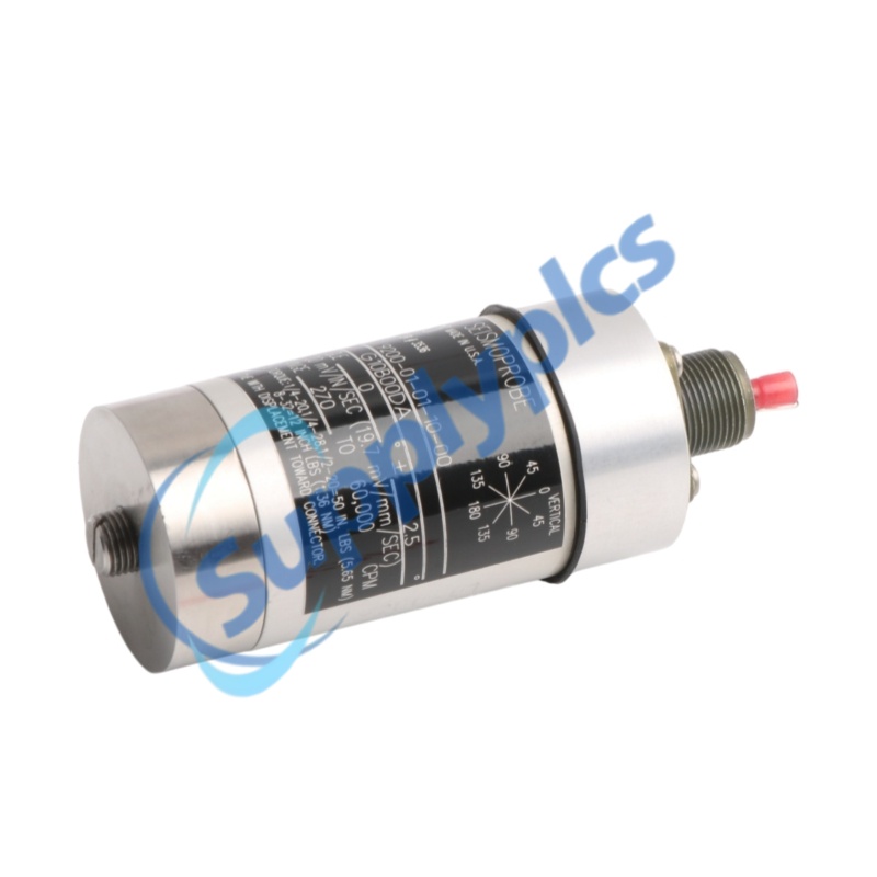
The nameplate and quotation should show 9200-01-01-10-00: 0 degree orientation, 4.5 Hz minimum frequency, top mount, M10x1 circular base and no approvals.
Q2. How can New, Used and Refurbished stock be distinguished?
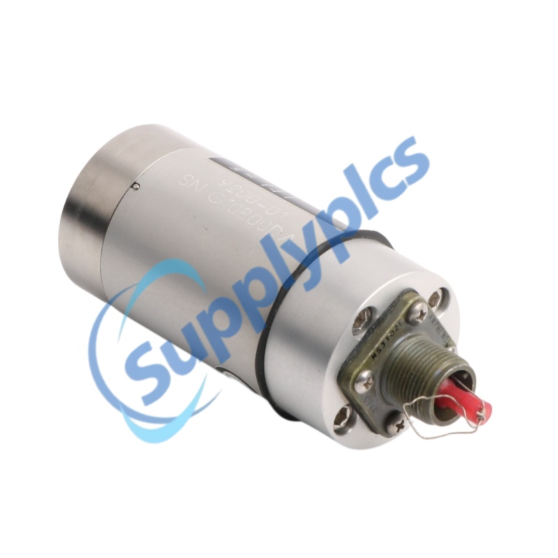
Request current photos of the case, top connector, M10x1 base and label. Check for mounting marks, connector wear, damaged threads or altered calibration identification.
Q3. What should be checked before approving a supplier?
Verify the registered company and beneficiary, traceable quotation, written return terms and the ability to provide time-stamped photos of this exact transducer.
Q4. Which specifications should an engineer confirm?
Confirm the 0 degree orientation, 4.5 Hz lower frequency, 20 mV/mm/s sensitivity, top-mount connection and M10x1 base.
Q5. What evidence should be requested before payment?
Ask for full sensor photos, connector and mounting-stud close-ups, the 9200-01-01-10-00 label and any available calibration or continuity record.
Q6. Can another 9200 suffix be substituted?
Not automatically. Orientation, minimum frequency, connector or cable, mounting base and approval options change installation and signal behavior.

Recommend Models

Recommend Model
AM/EB0000000B
SPR-8695PS
GW4K30KIT
2300-192-00-02
5365EWP01
IEM-3000-8FM
ABB MT70 GHQ6050059R0006
STDU48
Ey-Io570F001 Modu570
VI-PUFF-CUU
ABB 1SAP240000R0001 DI524 F0
QUINT-UPS/24DC/24DC/10 / 2320225
01BN766436
ABB 200-AIO
6760280 AE03
3HE05832CAAA01 SXP3104EX-A8-W
OAC-DT-2000-DMV
45-123
02A00H050
TMS13AMP
K1225
4GSTLS
RV033873300
XB12
AIP578-S1 S9390DH-00
MTK15-485
2182-227
IRM-S02TH
AES75-12
ADV151-P10
VS-5FDT-1
DVI-M PN:26-584-01
SPR-S8EZ
ABB PM571 / 1SAP130100R0170
ALLEN-BRADLEY 1756-PB75R/A
50006972
RK-300
ASY0001241
R1L-B
VT8000 3.0/USB-C
ABB TU516-H / 1SAP215000R0001
ABB 3AXD50000033277
1404-M505A-DNT
SXWAO8XXX10001 AO-8
BC8100 KL1104 KL1408 KL2134
MOD2DM
18E-882VMVM
CGSS1A6C2R1X
3SB5235-6HD10
1SDA067417R1
5642-50
IIR-M-RCT-P1
ABB 498A020G01 FT1-073
CLLYUB4024S
704015/0-154-22
025 32191 000
51401496-100
130806H-029
ES4/240/FC
ABB 6197-102-500

Get a Free Quote

Our representative will contact you soon.
Email
Name
Mobile
Company Name
Message
0/1000

Get a Free Quote

Our representative will contact you soon.
Email
Name
Mobile
Company Name
Message
0/1000