Product Name:Analog Input Module
Brand Name: ICS TRIPLEX
Model Number:T8461C
Country of Origin:USA
Warranty: 12 Months
Whatsapp:+86 18159889985
Email:[email protected]

Brand Name: |
ICS TRIPLEX |
Model Number: |
T9432 |
Country of Origin: |
USA |
Packaging Details: |
Original new Factory Sealed |
Delivery Time: |
Delivery time in stock |
Payment Terms: |
T/T |
|
Sales Manager: |
Stella |
|
Send an email: |
|
|
Contact in Whatsapp: |
|
Specification |
Details |
|
Module Type |
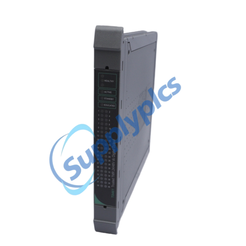
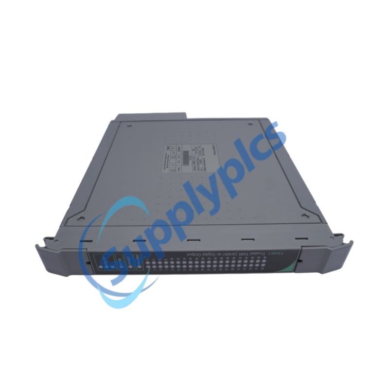
Trusted Triple Modular Redundancy (TMR) 24 Vdc / 48 Vdc Digital Output Module |
|
Number of Output Channels |
40 independent TMR digital output channels |
|
Output Voltage (Nominal) |
24 Vdc or 48 Vdc (per-channel configurable) |
|
Output Voltage Operating Range |
24 Vdc mode: 18 – 32 Vdc; 48 Vdc mode: 36 – 56 Vdc |
|
Output Type |
Solid-state (MOSFET), six-element voted switch array per channel |
|
Continuous Output Current per Channel |
0.75 A (max) |
|
Maximum Current per Power Group |
6 A (8 channels per group) |
|
Minimum Load Current |
25 mA (for line monitoring) |
|
Backplane Power Supply Voltage |
20 – 32 Vdc |
|
Isolation |
2500 V impulse withstand opto/galvanic isolation barrier |
|
Heat Dissipation |
5 W (max, typical) |
|
Diagnostic Functions |
Open-circuit, short-circuit, over-current detection; stuck-on and stuck-off tests |
|
Sequence of Events (SOE) |
On-board, 1 ms resolution |
|
Power Grouping |
Five isolated groups, eight outputs each |
|
Line Monitoring |
Per-channel automatic line monitoring |
|
Hot-Swap Support |
Yes (Companion Slot or SmartSlot configurations) |
|
Operating Temperature |
0 °C to +60 °C (standard); extended –40 °C to +70 °C (T8461C) |
|
Storage Temperature |
–25 °C to +70 °C (–13 °F to +158 °F) |
|
Relative Humidity |
10 % – 95 % (non-condensing) |
|
Dimensions (H × W × D) |
266 mm × 31 mm × 303 mm (10.5 in × 1.2 in × 12.0 in) |
|
Weight |
≈ 1.3 kg (2.7 lb) |
|
Certifications |
TÜV certified IEC 61508 SIL 3, ATEX, IECEx, UL Class I Div 2 |
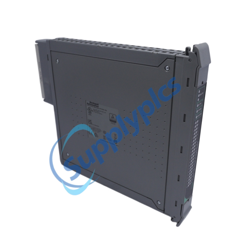
The ICS TRIPLEX T8461C is a Trusted TMR 24 Vdc / 48 Vdc digital output module that drives 40 independent field devices. Each output channel uses triple‑redundant circuits with 2‑out‑of‑3 (2oo3) hardware voting, eliminating single points of failure. On‑board diagnostics include automatic line monitoring (open/short circuit detection), over‑current protection without external fuses, and 1 ms Sequence of Events (SOE) recording. The T8461C supports hot‑swap replacement via Companion Slot or SmartSlot configurations and is TÜV certified to IEC 61508 SIL 3, making it ideal for the most demanding safety instrumented functions in Emergency Shutdown (ESD) and Fire & Gas (F&G) systems.
Emergency Shutdown Systems (ESD) – direct control of safety‑critical solenoid valves, dump valves, and shutdown relays in refineries, LNG plants and chemical facilities
Fire & Gas (F&G) Protection – actuation of fire‑fighting equipment (sprinklers, deluge valves), audible/visual alarms and ventilation dampers
Burner Management Systems (BMS) – energising flame safety shut‑off valves and initiating burner purge cycles in boilers and furnaces
Turbine Control – driving overspeed trip solenoids, emergency stop circuits and lubrication system cut‑offs for gas and steam turbines
High‑Integrity Process Control – controlling critical actuators in batch reactors, pipeline block valves and compressor anti‑surge systems
SmartSlot / Companion Slot Configurations – providing 1oo1 non‑redundant, 1oo2 redundant or online replaceable output control within a Trusted I/O chassis
40 TMR output channels – 40 fully triple‑modular redundant digital outputs, each with six‑element voted switch array
IEC 61508 SIL 3 certified – TÜV approved for safety instrumented functions with first‑fault fault tolerance and second‑fault fail‑safe behaviour
Selectable 24 Vdc or 48 Vdc operation – per‑channel software‑configurable output voltage (18–56 Vdc range)
Automatic line monitoring – open‑circuit and short‑circuit detection per channel; no‑load faults reported to the application
Automatic over‑current protection – electronic per‑channel current limiting and self‑latching short‑circuit fault protection – no external fuses required
2500 V opto‑galvanic isolation – between field side, logic side and the Inter‑Module Bus
On‑board Sequence of Events (SOE) – 1 ms resolution event logging for each output state change
Hot‑swap capability – online module replacement using dedicated Companion Slot (adjacent) or SmartSlot (shared spare)
Five isolated power groups – each group of eight outputs has independent field supply and return; groups isolated to 50 V reinforced
Comprehensive on‑line diagnostics – continuous self‑test of output switches, gate modulation monitoring, stuck‑on / stuck‑off detection
Front panel LED indicators – per‑channel status (on/off, line fault, channel fault) plus module healthy, active, standby, educated LEDs
TMR fault handling – first fault ‑ fault tolerant (system continues); second fault ‑ fail‑safe (output group de‑energises via group fail‑safe switch)
Wide temperature range – standard 0 °C to +60 °C; extended –40 °C to +70 °C (T8461C)
2‑out‑of‑3 (2oo3) output voting – three independent processor slices (A, B, C) each receive output data from the Trusted TMR Processor; a hardware voter selects the majority value. If one slice fails or diverges, the remaining two slices maintain correct output control.
Six‑element fail‑safe switch topology – each output channel is constructed as three fail‑safe switch pairs (one pair per slice). Each pair comprises a normally‑open (N.O.) upper switch (controlled by its own slice) and a normally‑closed (N.C.) lower switch (controlled by the upstream slice). This arrangement ensures that even after an entire slice failure, two remaining slices continue to energise the load.
Gate voltage modulation diagnostics – while the output is energised, the module modulates the gate voltage of each switch (one at a time) and analyses the resulting small AC signal to determine on‑resistance, threshold voltage and switch health. The load current is not interrupted.
Automatic line fault detection – voltage and current are measured continuously. Energised outputs report open circuit (no load), short circuit (over‑current latched), or normal. De‑energised outputs optionally perform a partial energisation (less than 2 V or 100 mA) to measure loop resistance; a short circuit (resistance < 40 Ω) is detected and reported.
Group fail‑safe switches – each power group (8 channels) includes a triple‑parallel group fail‑safe switch (one per slice). If two or more slices detect that an output cannot be de‑energised (stuck‑on), any slice can command its own GFSS and those of the other two slices to open. If two slices act, the last remaining GFSS opens, de‑energising the entire group.
Sequence of Events (SOE) – the module timestamps each output state change (on→off, off→on) with 1 ms resolution. When polled by the TMR Processor, the timestamp and new state are uploaded and written to the system SOE log.
Housekeeping monitoring – internal voltages (24 V backplane, 8 V slice supplies, field supply per group), board temperatures (HIU, FIU per group), and current consumption are continuously measured and reported via housekeeping registers (Rack 7) for diagnostic purposes.
Active / Standby changeover – when a secondary T8461C is installed in a Companion Slot, the TMR Processor educates the standby module. Upon fault detection in the active module, the processor performs a bumpless changeover: the standby is configured, dynamic changeover data (COD) is transferred, and the standby becomes active without output interruption.
Cold start behaviour – after installation, the module boots, is educated by the processor, and then the Run LED becomes amber. Outputs are not energised. Pressing the processor fault reset button sets the module to active (Run LED green) and outputs follow the application logic.
Q1: What is the maximum output current per channel for the T8461C?
A1: The T8461C provides 0.75 A continuous per channel at 60 °C ambient. The maximum current per power group (8 channels) is 6 A. Some literature quotes 0.5 A at extended temperature ranges.
Q2: Can the T8461C be replaced while the system remains powered?
A2: Yes. The T8461C supports hot‑swap replacement using a dedicated Companion Slot (adjacent slot with common field wiring) or a SmartSlot configuration (shared spare slot with a temporary jumper cable).
Q3: Does the T8461C require external fuses for short‑circuit protection?
A3: No. The T8461C provides automatic electronic over‑current protection per channel. Upon detection of a sustained over‑current condition, the channel latches off and reports a short‑circuit fault. No external fuses are required.
Q4: Can the T8461C detect open‑circuit and short‑circuit faults in field wiring?
A4: Yes. The T8461C includes per‑channel automatic line monitoring. Energised outputs detect no‑load (open circuit). De‑energised outputs can be configured to perform a partial energisation to measure loop resistance; a resistance below 40 Ω is reported as a short circuit.
Q5: What is the isolation voltage of the T8461C between channels and the backplane?
A5: The T8461C provides 2500 V impulse withstand opto‑galvanic isolation between the field side and the logic side (Inter‑Module Bus). Power groups are isolated from each other to 50 V reinforced continuous.
Enquiry Now : [email protected]