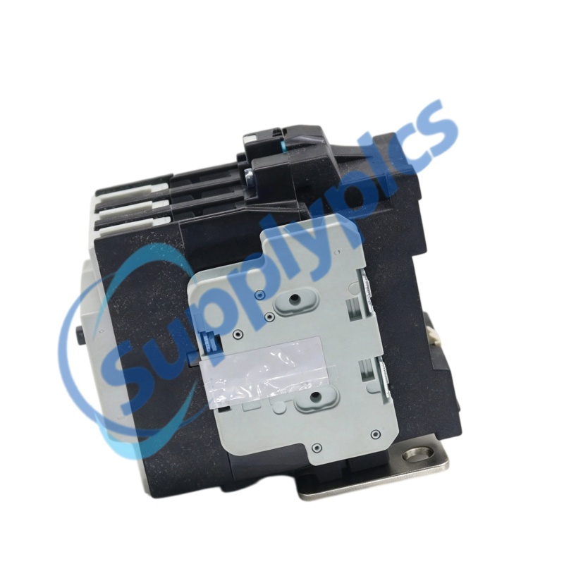
Exact configuration
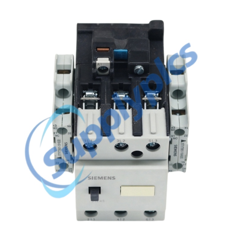
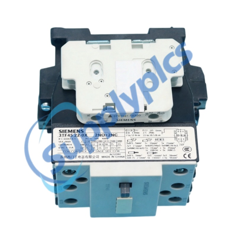
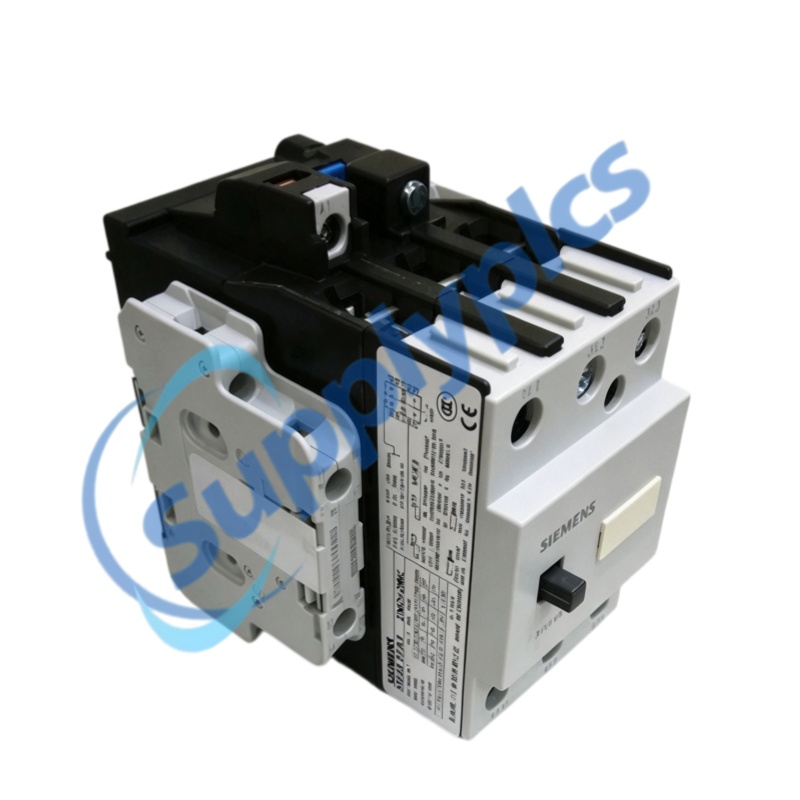
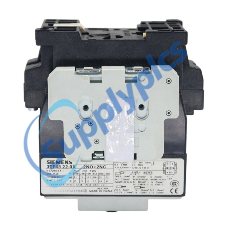
Siemens 3TF series, complete model 3TF4522-0XM0. The 22 contact arrangement provides 2 NO + 2 NC auxiliary contacts.
|
Switching duty
The 3TF45 frame is rated for 18.5 kW at 400 V AC-3 and 20 kW at 415 V AC-3.
|
Mechanical format
AC-operated screw-terminal version; body dimensions 82 x 103 x 104 mm and approximate weight 760 g.
|
Mounting
Snap mounting on a 35 mm standard rail or surface mounting with two M4 screws.
|
|
Complete model
|
3TF4522-0XM0
|
|
Brand
|
Siemens
|
|
Product family
|
3TF45 AC contactors
|
|
Product type
|
Three-pole AC contactor with 2 NO + 2 NC auxiliary contacts
|
|
Connection
|
Screw terminals
|
|
Dimensions (W x H x D)
|
82 x 103 x 104 mm, AC-operated screw-terminal version
|
|
Weight
|
Approx. 760 g, AC-operated
|
|
Mounting
|
35 mm standard mounting rail or plain surface with two M4 screws
|
|
Mounting footprint
|
45/49 x 75 mm
|
|
Main circuit insulation voltage
|
AC 690 V
|
|
Operational current AC-1
|
55 A at 55 deg C
|
|
Continuous current
|
45 A, open and enclosed type
|
|
Motor rating AC-3 at 400 V
|
18.5 kW
|
|
Motor rating AC-3 at 415 V
|
20 kW
|
|
Auxiliary contact arrangement
|
2 NO + 2 NC
|
|
Auxiliary circuit insulation voltage
|
AC 690 V
|
|
Auxiliary operational current AC-11
|
5.6 A at AC 230 V
|
|
Protection rating
|
IP00 to IEC 60529; finger-safe to DIN VDE 0106, Part 100
|
|
Operating temperature
|
-25 to +55 deg C
|
|
Storage temperature
|
-50 to +80 deg C
|
|
Standards
|
DIN VDE 0660; IEC 60947
|
|
AC-3 motor ratings
11 kW at 230 V; 12 kW at 240 V; 18.5 kW at 400 V; 20 kW at 415 V; 25 kW at 500 V; 23 kW at 690 V.
|
Main circuit
Rated insulation voltage AC 690 V. Rated operational current AC-1 is 55 A at 55 deg C.
|
|
Horsepower ratings
Three-phase motors at 60 Hz: 10 hp at 200 V, 15 hp at 230 V, and 25 hp at 460 V or 575 V.
|
Short-circuit coordination
gL/gG fuse links: 80 A for assignment type 1 and 63 A for assignment type 2; 25 A for the listed non-welding conditions.
|
|
Main poles
Three main switching poles use terminals 1L1-2T1, 3L2-4T2, and 5L3-6T3.
|
Auxiliary contacts
2 NO contacts at 13-14 and 43-44; 2 NC contacts at 21-22 and 31-32.
|
|
Main conductors
Solid 1 to 16 mm2; stranded 2.5 to 25 mm2 for one terminal connection. Strip length 10 mm; tightening torque 2.5 to 3.0 Nm.
|
Auxiliary conductors
Solid 2 x 0.5 to 1 mm2 or 2 x 1 to 2.5 mm2. Strip length 10 mm; tightening torque 0.8 to 1.4 Nm.
|
|
Rail or panel mounting
Snap the contactor onto a 35 mm standard mounting rail to DIN EN 50022, or fix it to a plain surface with two M4 screws, plain washers, and spring washers.
|
Permissible position
Vertical mounting is permitted, with lateral deviation up to 90 deg and forward or backward inclination up to 22.5 deg.
|
|
Clearance and enclosure
Maintain the minimum clearances shown in the dimensional drawing. Use an enclosure where dirt, dust, or aggressive atmosphere may reach the contactor.
|
Terminal preparation
Use 75 deg C copper wire. Tighten every terminal screw, including unused screws, and follow the specified conductor cross-sections and torques.
|
|
Inspection
After a short circuit, inspect the main contacts and arc chute. Do not operate the device by pressing the position indicator while voltage and load are applied.
|
Replaceable parts
Main contacts, arc chute, magnet coil, and auxiliary contact blocks are replaceable. Use original spare parts.
|
|
Contact condition
Dark or rough contacts can remain functional. Do not refinish or grease them; replace them when carrier material becomes visible.
|
Cleaning and return to service
Remove dust by suction. Keep magnet pole faces clean, and return the contactor to service only with the arc chute fitted.
|
|
1
|
How can a buyer verify that the offered item is exactly 3TF4522-0XM0?
Request clear photos of the front rating plate, side label, coil label, and terminal markings. The complete code must read 3TF4522-0XM0, and the contact layout must show three main poles plus 2 NO and 2 NC auxiliary contacts.
|
|
2
|
How can New, Used, and Refurbished condition be distinguished for this contactor?
Ask for current high-resolution photos of the arc chute, screw terminals, housing, position indicator, and coil label. Terminal marks, tool wear, dust, discoloration, or replaced contact parts can indicate prior service or refurbishment.
|
|
3
|
How should a purchaser check whether the supplier is legitimate and reliable?
Verify the registered company identity, business address, bank-account beneficiary, traceable contact details, and a verifiable sales history. The quotation and invoice should state the exact model 3TF4522-0XM0 without a shortened code.
|
|
4
|
Which specifications should an engineer confirm before purchase?
Confirm the exact coil rating on the device nameplate, the 2 NO + 2 NC auxiliary arrangement, screw-terminal conductor ranges, 82 x 103 x 104 mm body size, 45/49 x 75 mm mounting footprint, 18.5 kW rating at 400 V AC-3, and IP00 protection.
|
|
5
|
What physical evidence should be requested before payment?
Request dated photos or video showing the complete nameplate, coil label, terminals 1L1 through 6T3, auxiliary terminals 13-14, 21-22, 31-32, and 43-44, the arc chute, and the actual packaging label.
|
|
6
|
Can a similar 3TF45 model or a different suffix replace 3TF4522-0XM0?
Not automatically. A different suffix or contact code may change the coil rating, terminal format, or auxiliary contact arrangement. Replacement is acceptable only after the engineer confirms the complete code, coil data, 2 NO + 2 NC contacts, dimensions, mounting, and load ratings.
|
|
RK-4B
|
10-b13
|
3RF2310-1AA04-0KN0
|
|
1SVR427025R0000
|
MU-NKD005 / 51195153-005
|
XL50
|
|
8816001039 USB-I485
|
W7754P1000
|
JO8
|
|
PCS095.s
|
IC695ALG616-LF
|
CDI161
|
|
P61 MA1 80036035
|
FP-TC-120 186424A-01
|
ABB 1SAP240800R0001
|
|
LVOS-0-10-PWM-DIN 0-10-PWM-DIN
|
TR-MG/500cc
|
NR500-S3G
|
|
UD2A-EDID-S
|
TSXCDP303
|
LEGRAND 002640
|
|
S50 ,A05131200980
|
EW100 EM100
|
46940C-5 AA25A-024L-050T120
|
|
AD2016AVIM-4
|
8817R
|
ROF 131 4414/4R8B
|
|
M1000/3.0
|
PT5402
|
3RT1046-1AL20
|
|
IZM-SEC-TB15
|
DFP21B PN:08242402
|
2CDG110055R0011
|
|
MNN-50-100
|
TH-T3A-L20F-GABF
|
TP-10/VC
|
|
CA5-01 1SBN010010R1001
|
ABB 2CDG120041R0011
|
15B10904G1
|
|
MT 701 V2.0 6825
|
EY-IO572F001
|
200-F 450-00197-903
|
|
ANN840
|
MSP2400.232
|
M/P960.1 DC30V
|
|
NK105
|
IO-351-A 96161720-V01
|
3HE09327AARA01 ROHS6/6-40/85C
|
|
PLC-XP55
|
DO-FA-12 SXDOA12X10001 SXWTBIOW110001
|
ABB CM574-RS 1SAP170400R0201
|
|
SM30SRL
|
CLXI-1MC4
|
100Base-T
|
|
TM221M16T M221-16io
|
OLS-120
|
SP3-GT35
|
|
nt12dmc
|
PS2-R7A 4351300
|
LJ-G5001
|
 EN