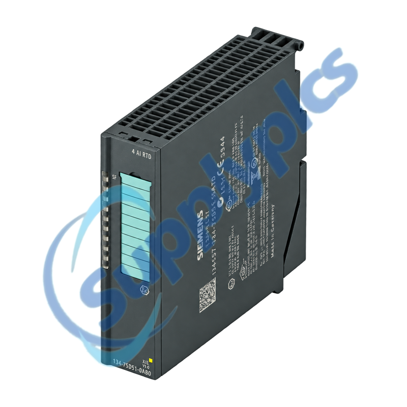
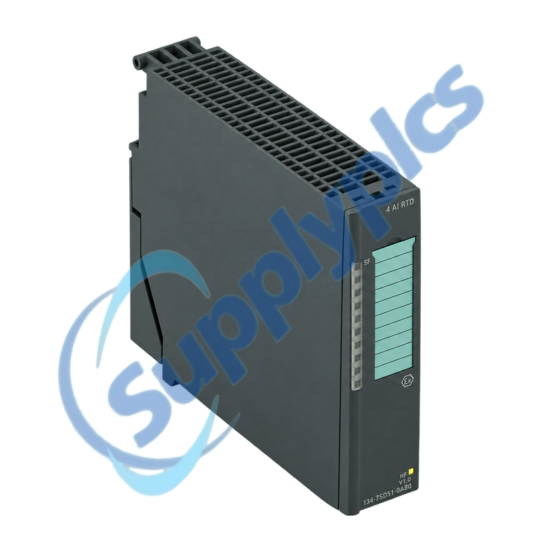
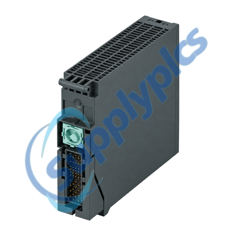
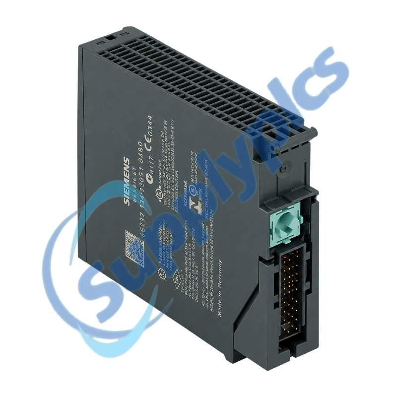
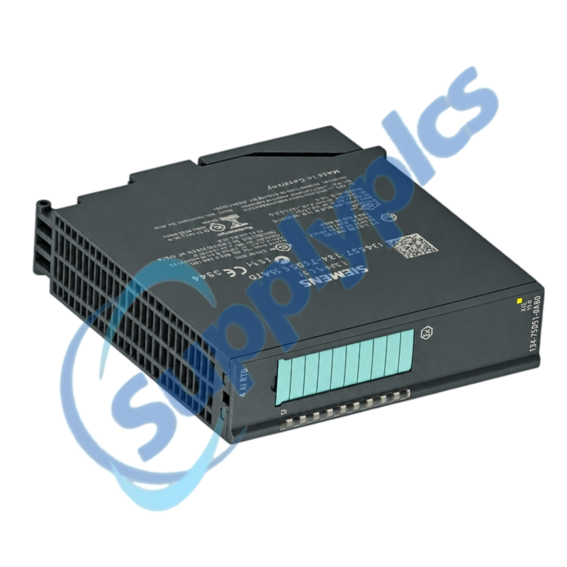
Four-channel intrinsically safe RTD and resistance input module for ET 200iSP
The 4AI RTD electronic module measures Pt100 and Ni100 resistance thermometers or resistance signals on four channels. It supports 2-, 3- and 4-wire connections and is installed on TM-IM/EM or TM-EM/EM terminal modules in approved ET 200iSP hazardous-area systems.
Ex-system compatibility check: Verify the complete order number, terminal-module type and mechanical coding, hazardous-area zone, ATEX and IECEx requirements, sensor entity parameters, 2-, 3- or 4-wire circuit, channel parameterization and the ET 200iSP station configuration before replacement.
RTD Wiring
6ES7134-7SD51-0AB0 is the SIMATIC ET 200iSP 4AI RTD electronic module for temperature and resistance measurement in intrinsically safe installations. The module provides four channels with 15-bit plus sign resolution and linearization for supported resistance thermometers.
Installation quality directly affects measurement accuracy and explosion protection. The sensor wiring method, compensation, intrinsic-safety entity calculation, cable segregation, enclosure protection and terminal-module coding must all be checked before commissioning.
Match the configured measuring method to the actual sensor and cable arrangement.
Lead compensation
Use the correct 2-, 3- or 4-wire scheme and parameterization; uncompensated lead resistance can shift the indicated temperature.
Channel assignment
Label M+, M-, IC+ and IC- conductors by channel and compare the terminal positions with the ET 200iSP wiring diagram.
Signal validation
Check the sensor resistance with an approved method and compare the raw value, engineering unit and diagnostic status before recalibration.
Ex Installation
Preserve intrinsic-safety segregation, entity limits and enclosure protection during service work.
Entity parameters
Confirm Uo, Io, Po, Co and Lo against the connected sensor, cable capacitance and inductance and the applicable certificate.
Cable separation
Route intrinsically safe and non-intrinsically safe circuits in the required separate ducts and follow EN 60079-14 and local rules.
Module handling
Inspect damage and terminal coding, observe Zone 1 and Zone 2 enclosure requirements and follow the approved hot-swap conditions.
Specifications
Product type designation
SIMATIC ET 200iSP 4AI RTD
Order number
6ES7134-7SD51-0AB0
Input channels
4
Supported sensors
Pt100 and Ni100 RTDs; resistance measurement
Wiring methods
2-wire, 3-wire and 4-wire
Resolution
15 bits plus sign
Measuring current
Approximately 1 mA
Terminal modules
TM-IM/EM or TM-EM/EM
Isolation
Channels isolated from backplane and power bus; not channel-to-channel
Load-current consumption
Maximum 22 mA
Power loss
Approximately 0.4 W
Hazardous-area use
Approved ET 200iSP installation with specified Ex conditions
How can I verify that 6ES7134-7SD51-0AB0 matches the installed ET 200iSP station?
Match the full module label, terminal-module type and mechanical coding. Compare the configured 4AI RTD hardware entry, hazardous-area approvals, channel ranges and the actual 2-, 3- or 4-wire sensor circuits.
Q2
Why can a Pt100 channel read incorrectly after installing 6ES7134-7SD51-0AB0?
Check whether the project and field wiring both use the same 2-, 3- or 4-wire method. Verify lead compensation, M and IC terminal positions, sensor range and channel parameterization before applying an offset or replacing the sensor.
Q3
What should be checked before connecting a Zone 0 sensor to 6ES7134-7SD51-0AB0?
Confirm the ET 200iSP installation and enclosure are approved for the area, then complete the intrinsic-safety entity comparison for voltage, current, power, capacitance and inductance including the field cable. Follow the applicable certificate and EN 60079-14.
Q4
How should a channel fault on 6ES7134-7SD51-0AB0 be isolated without defeating intrinsic safety?
Use approved safe-area or intrinsically safe test methods and first read the station diagnostics. Inspect terminal seating, cable segregation and sensor continuity, then compare the affected channel with a known-good channel without bridging Ex circuits.
Q5
Can 6ES7134-7SD51-0AB0 be inserted or removed while the ET 200iSP station is operating?
The official instructions permit handling in Zone 1 and Zone 2 only under the defined enclosure and operating conditions, with the enclosure opened only briefly. Follow the site permit, national rules and ET 200iSP manual rather than treating it as unrestricted hot swap.
Q6
What evidence should accompany a replacement request for 6ES7134-7SD51-0AB0?
Provide the full order number, terminal-module and station details, hazardous-area classification and certificate basis, sensor type, wiring method, entity calculation, channel parameters and the observed diagnostic code or measured error.

 EN