Get a Free Quote

Our representative will contact you soon.
Email
Name
Mobile
Company Name
Message
0/1000
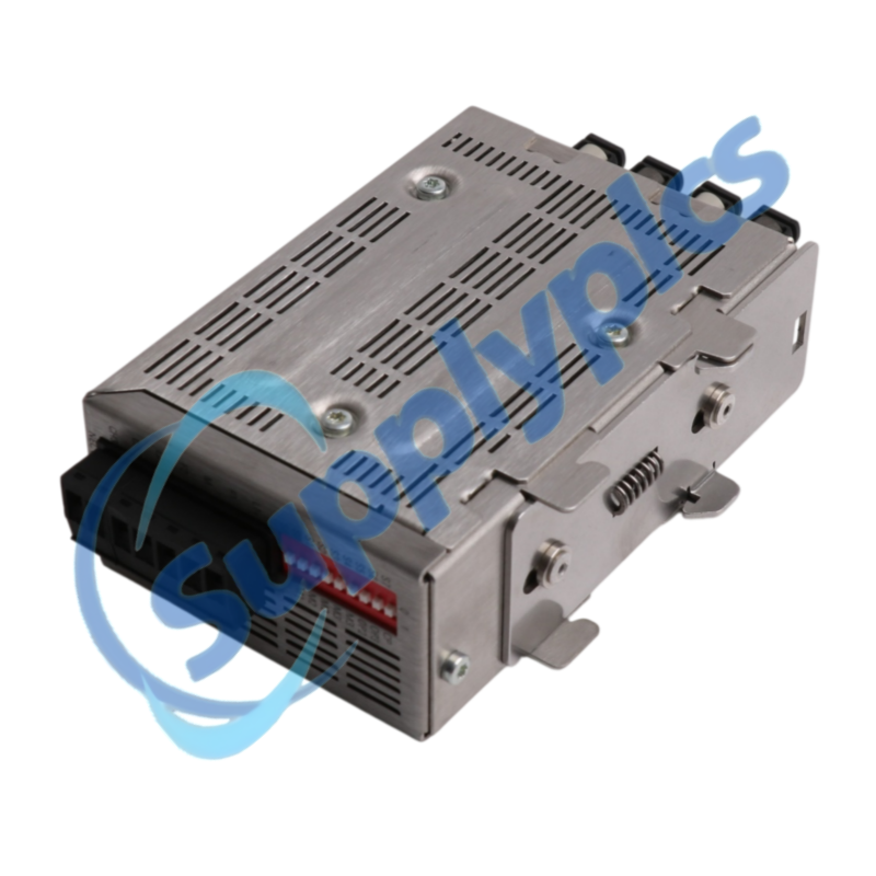
siemens 6gk1503 3cb00 simatic net profibus olm g12 v4 0 optical link module-0

SIEMENS

Home >  Products >  SIEMENS

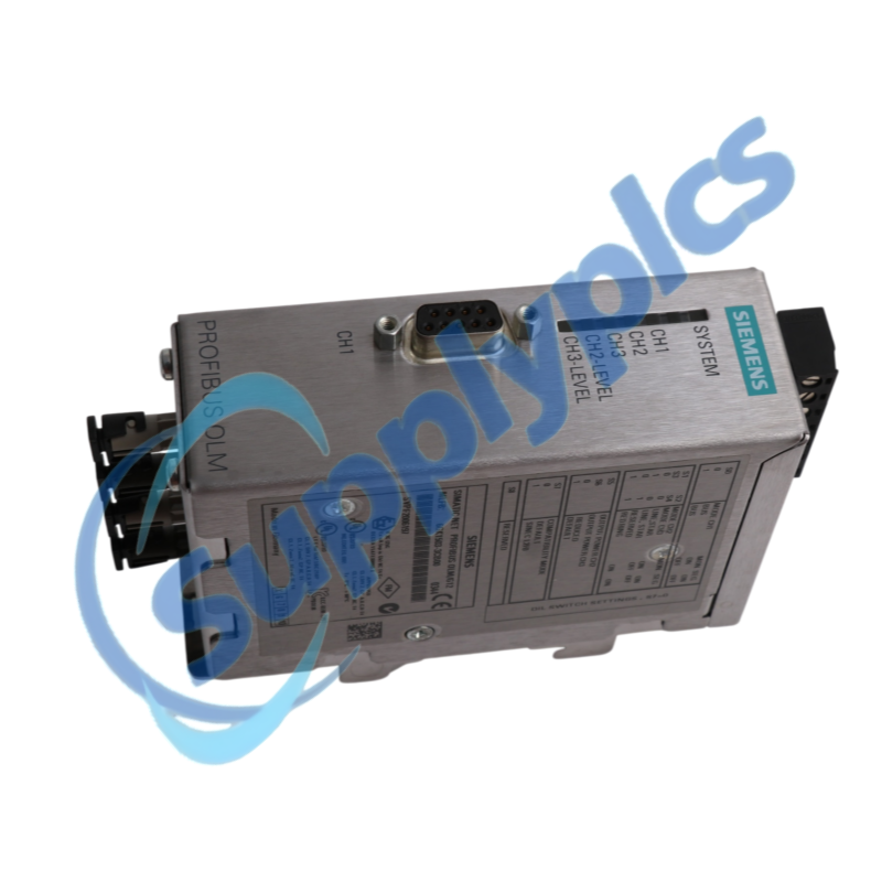
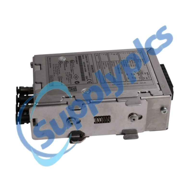
Siemens 6GK1503-3CB00 PROFIBUS OLM/G12 V4.0

Product Name: SIMATIC NET PROFIBUS OLM/G12 V4.0 Optical Link Module
Brand Name: Siemens
Model Number: 6GK1503-3CB00
Place of Origin: Germany
Warranty: 12 Months
Whatsapp: +86 180 2077 6782
Appurtenance:
  • Overview
  • Fiber Guide
  • Specs
  • Supply
  • FAQ
  • Other Products
  • Recommended Products
PROFIBUS optical link module with one RS485 and two glass-fiber channels
The OLM/G12 V4.0 converts PROFIBUS electrical signals to 860 nm multimode optical links through BFOC connectors. It supports linear, star and redundant optical topologies, making fiber type, DIL switch settings and optical path condition central to a reliable installation.
Optical path check: Confirm the G12 V4.0 variant, 50/125 or 62.5/125 micrometer multimode fiber, BFOC connectors, partner module, link length, PROFIBUS rate, DIL switch positions, redundant topology and signaling-contact wiring before replacement.

Fiber Guide

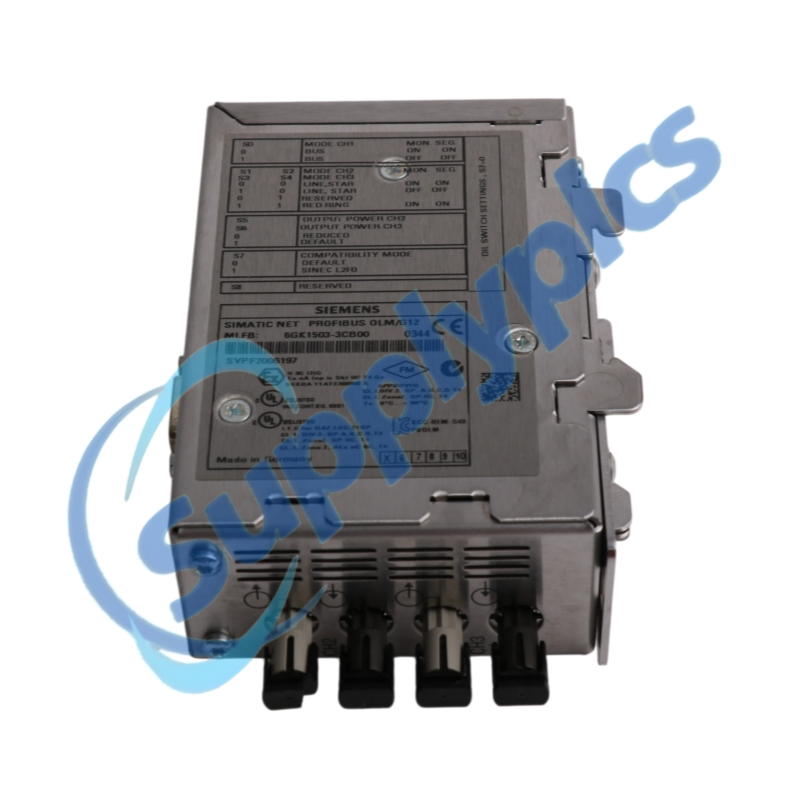
6GK1503-3CB00 is the SIMATIC NET PROFIBUS OLM/G12 V4.0 with one electrical RS485 interface and two optical glass-fiber interfaces. The four BFOC sockets form two transmit and receive channels for multimode links up to the verified system distance.
Service work should begin with a fiber map that identifies channel, Tx and Rx direction, partner module and route. Record the DIL switches, LEDs, signaling contact and power connections, then clean and inspect every optical connector before measuring or replacing the module.
Treat each optical channel as a paired transmit and receive path with a known partner and budget.
Media match
Verify multimode fiber core size, BFOC connector quality, wavelength and the approved far-end OLM type.
Channel map
Label channel 1 and channel 2, Tx and Rx direction, partner location, route length and any patch connection.
Topology settings
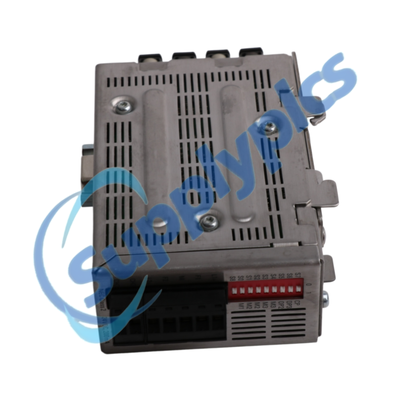
Record line, star or redundant-ring function and every DIL switch position before power is removed.
LEDs and the signaling contact help distinguish power, bus and optical-path faults.
Connector condition
Inspect and clean BFOC faces, respect the bend radius and reseat each connector without swapping Tx and Rx.
Signal evidence
Record channel LEDs, system LED and signaling-contact state under normal operation and during the fault.
Path isolation
Test one approved path at a time and compare both local and remote channel indications before replacing electronics.

Specs

Product type designation PROFIBUS OLM/G12 V4.0 Order number 6GK1503-3CB00
Electrical interface 1 x RS485 Optical interfaces 2 x glass-fiber channels
Optical connectors 4 x BFOC sockets Optical wavelength 860 nm
Supported fiber 50/125 or 62.5/125 micrometer multimode Maximum link reference Up to 3 km with approved fiber conditions
PROFIBUS rate 9.6 kbit/s to 12 Mbit/s Supply range 18 to 32 V DC
Operating temperature 0 to 60 degrees C Degree of protection IP40

Supply

Quotation
Current price and availability
Payment
T/T or agreed terms
Lead time
Confirmed with quotation
Shipping
DHL, FedEx, UPS or agreed freight
Warranty
12 months

FAQ

Q1
How can I confirm that 6GK1503-3CB00 matches the installed optical PROFIBUS link?
Match the complete OLM/G12 V4.0 order number, four BFOC sockets, 860 nm multimode fiber and the partner OLM type. Record the fiber core size, DIL switches, topology and signaling-contact wiring before ordering.
Q2
Why can an optical channel remain dark after installing 6GK1503-3CB00?
Check that Tx at one module reaches Rx at the partner, then inspect and clean both BFOC connectors and verify the multimode fiber type. Compare local and remote channel LEDs and confirm that the DIL switches match the intended link mode.
Q3
What should I inspect when 6GK1503-3CB00 reports intermittent PROFIBUS faults at higher baud rates?
Review the total optical path, patch points, connector contamination, bend radius and fiber damage, then compare the partner-module status. Confirm the PROFIBUS timing and topology limits for the selected transmission rate before changing the module.
Q4
How should 6GK1503-3CB00 be prepared for a redundant optical ring replacement?
Document both channel directions, ring partner sequence, DIL switch positions and normal LEDs. Replace the module during a controlled window, restore one path at a time and prove that ring interruption and recovery are reported correctly.
Q5
Why can the signaling contact on 6GK1503-3CB00 indicate a fault while some PROFIBUS traffic still passes?
A monitored power or optical channel can be faulty while the remaining path continues to carry traffic. Check supply voltage, channel LEDs, fiber partners and the configured monitoring behavior before assuming the contact or module is defective.
Q6
How can I isolate whether 6GK1503-3CB00 or the fiber path is causing communication loss?
Record both-end LEDs, clean and reseat the connectors, verify Tx-to-Rx routing and test a known-good approved path or partner channel. Compare the result at both ends so a remote transmitter, damaged fiber and local receiver are not confused.

Other Products

IO113 EN837-1 033010-A
ABB 1KNU3000R1001 23BI61R1LF ESA047010 SM87HXB SY1178500 AM313830035
PN:05605120 GVAG-2VK1S SDO-0824
A9MEM3255 iEM3255 BX8000-0000 VFNC3S-2007PL
TZ350 APL28-0B4 162235-PR MS-VMA1630-1
BR6000-R06 8265674 SK3120115
SL5/1 SWB-23 / S9440BJ-01 SB-DN-EIB
87419544 ABB PNU32 ABB 1SD A0 66317
3051 03031-3023-0022 BK5250 N-ID8
XD26 MILLENIUM3 88974163 SXWDI16XX10001 SWP-99-2128-1-4-001

Get a Free Quote

Our representative will contact you soon.
Email
Name
Mobile
Company Name
Message
0/1000

Get a Free Quote

Our representative will contact you soon.
Email
Name
Mobile
Company Name
Message
0/1000