AVT combination module for SINAMICS medium-voltage converter actual-value channels
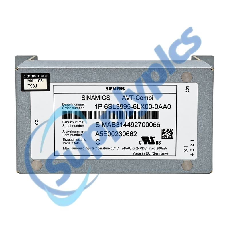
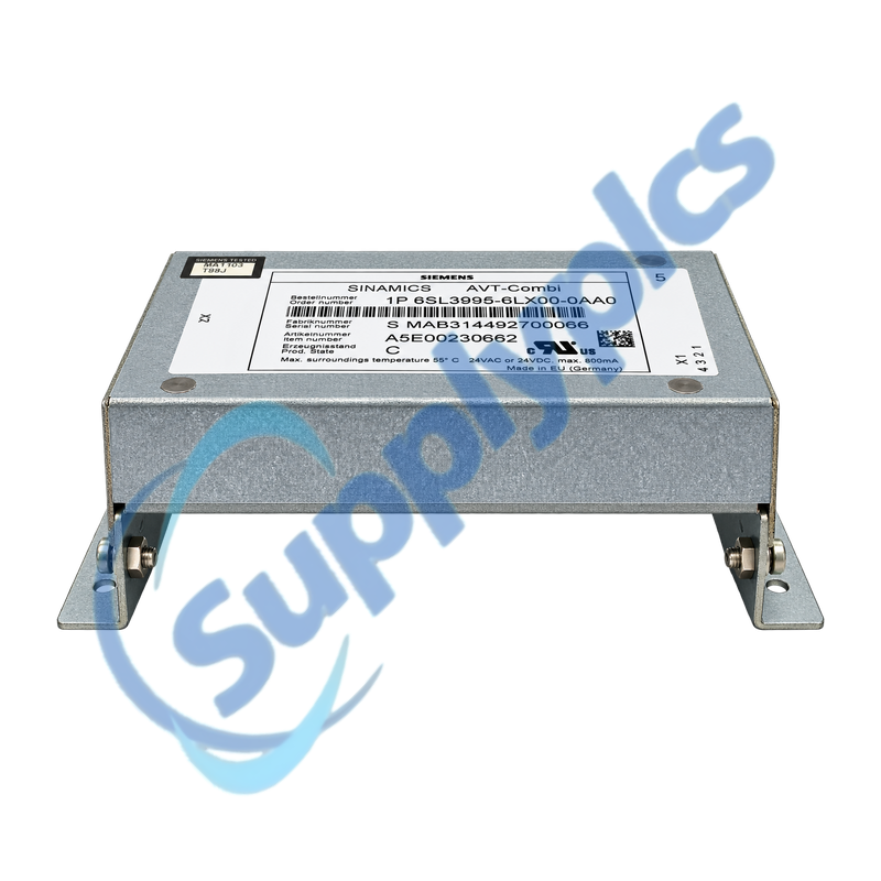
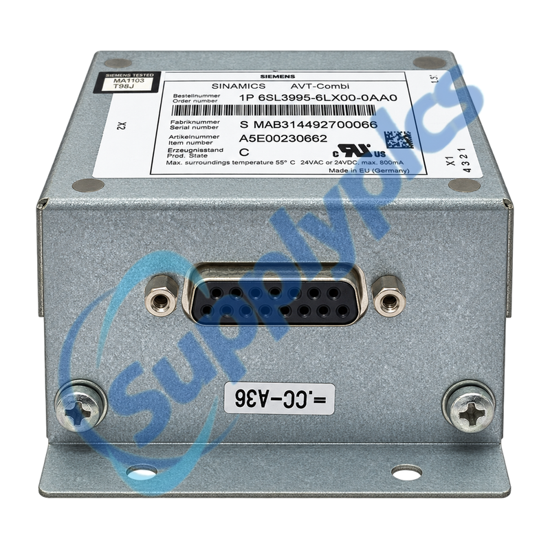
The AVT-Combi is used in a SINAMICS medium-voltage converter installation as part of the actual-value transmission chain. The exact Siemens nameplate identifies 24 VAC or 24 VDC auxiliary supply, maximum 800 mA and a maximum ambient temperature of 55 °C.
Converter-system check: Match the complete 6SL3995-6LX00-0AA0 label, item and serial numbers, production state, cabinet position, X1 and X2 wiring, actual-voltage and current-sensing circuit, 24 V auxiliary supply, CU320 project and converter circuit diagram before replacement.
AVT Integration
6SL3995-6LX00-0AA0 is a Siemens SINAMICS AVT-Combi module used inside a medium-voltage converter system. It is not a standalone low-voltage signal accessory; its function and wiring must be interpreted from the converter-specific circuit diagram and cabinet parts list.
Work on this assembly belongs to trained converter personnel because hazardous voltages may remain in auxiliary and sensing circuits. Preserve the component label, circuit references, connector map and fault evidence and verify the actual-value channels with the converter in the prescribed safe state.
Treat the module as part of a documented high-voltage measurement chain.
Cabinet identity
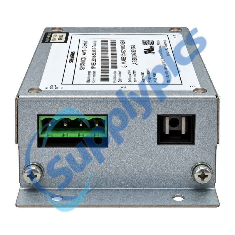
Record cabinet section, item code, X1 and X2 connector assignment, serial number and production state from the label.
Circuit relationship
Trace voltage sensing, ground-fault detection and current-sensing paths against the converter circuit diagram.
Project context
Preserve the CU320 project, parameter set, DRIVE-CLiQ topology and hardware trace data associated with the fault.
Signal Checks
Perform measurements only under the approved converter safety and commissioning procedure.
Auxiliary supply
Confirm the approved 24 VAC or 24 VDC source, polarity where applicable, grounding concept and stable supply under load.
Actual-value channels
Check that the measured signal and connector assignment agree with the circuit diagram; the official commissioning check limits AVT input to 3 V.
Fault evidence
Save alarms, STARTER or AOP messages, trace files and operating conditions before replacing the module.
Specifications
Product type designation
SINAMICS AVT-Combi
Order number
6SL3995-6LX00-0AA0
System family
SINAMICS medium-voltage converters
Primary role
Actual-value transmission combination module
Auxiliary supply
24 VAC or 24 VDC
Maximum current
800 mA
Maximum ambient temperature
55 °C
Key connections
X1 and X2; verify with converter circuit diagram
Commissioning reference
CU320 project and DRIVE-CLiQ topology
Actual-value check
AVT combination input voltage not above 3 V during official commissioning check
How can I verify that 6SL3995-6LX00-0AA0 belongs to the installed SINAMICS converter?
Match the full Siemens AVT-Combi label, item and serial numbers and production state with the cabinet parts list and circuit diagram. Confirm cabinet position, X1 and X2 wiring, CU320 project and actual-value channel assignment.
Q2
What should be recorded before disconnecting 6SL3995-6LX00-0AA0 from the converter cabinet?
Photograph the complete nameplate and both connectors, label every conductor and record the item code, circuit references and grounding. Save the CU320 project, alarms and hardware trace files before the approved isolation procedure begins.
Q3
Why can an actual-value fault remain after installing 6SL3995-6LX00-0AA0?
Check the 24 V auxiliary supply and connector assignment, then trace the voltage, current and ground-fault sensing paths against the circuit diagram. Review converter parameters and stored fault traces before assuming the replacement module is defective.
Q4
How should the input signal to 6SL3995-6LX00-0AA0 be checked during commissioning?
Only trained personnel should measure it under the SINAMICS GL150 safety procedure. Siemens instructs checking the actual-value channels with AVT combination input voltage not above 3 V; use the exact test point and reference defined by the circuit diagram.
Q5
What evidence is most useful for diagnosing an intermittent problem around 6SL3995-6LX00-0AA0?
Provide the alarm history, CU320 hardware trace files, supply measurements and operating conditions such as temperature and converter load. Include connector and cabinet photos and whether the signal changes with vibration, warm-up or auxiliary-supply switching.
Q6
Can 6SL3995-6LX00-0AA0 be treated as a simple plug-in spare during a shutdown?
No. The module is part of a medium-voltage converter measurement system, and hazardous voltages can remain in auxiliary circuits. Replacement requires the converter-specific circuit diagram, trained personnel and controlled verification of sensing and protective functions.

 EN