Get a Free Quote

Our representative will contact you soon.
Email
Name
Mobile
Company Name
Message
0/1000
siemens simatic s7 1200 6es7274 1xh30 0xa0 sim 1274 14 input simulator module original new-0

SIMATIC S7 Series

Home >  Products >  SIEMENS >  SIMATIC S7 Series

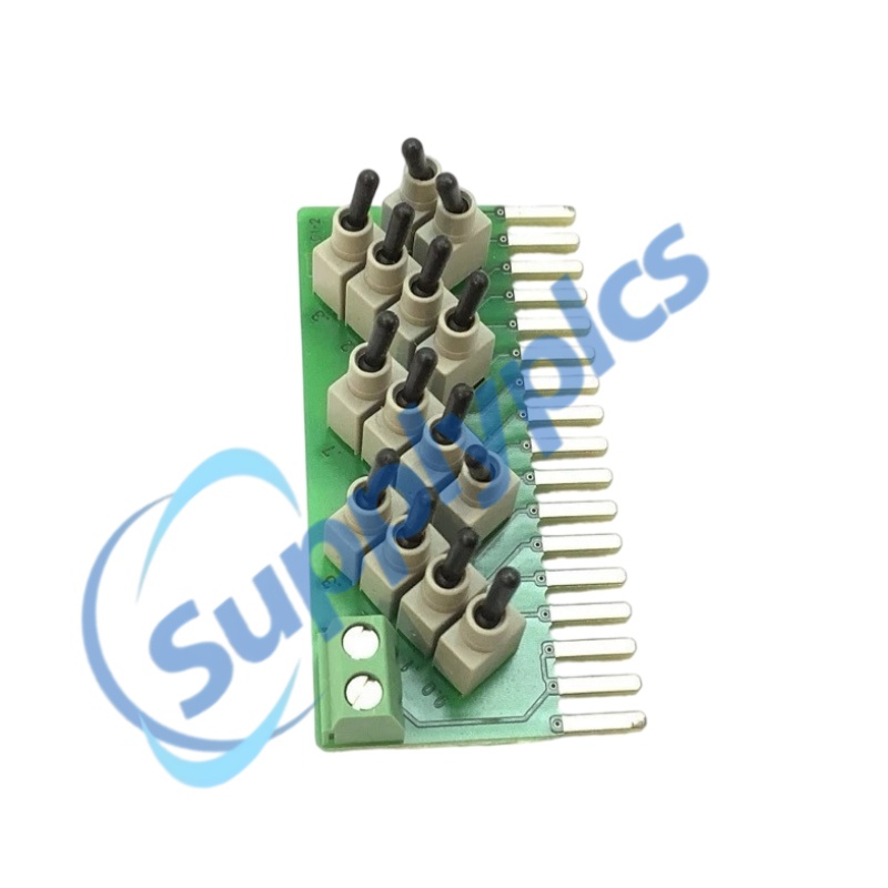
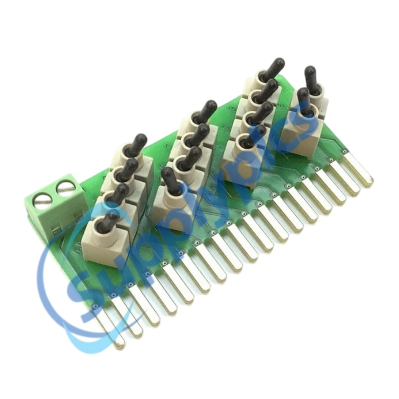
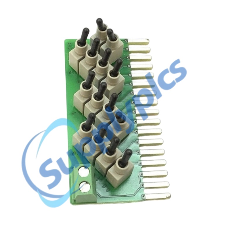
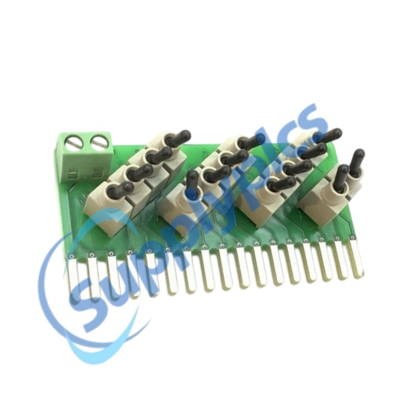
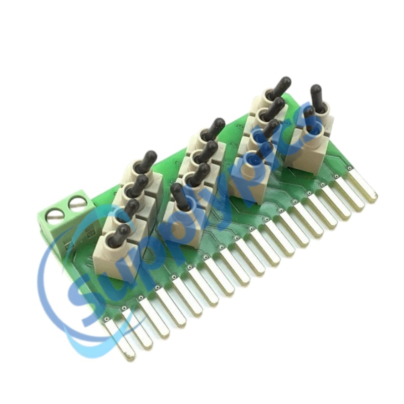
SIEMENS SIMATIC S7-1200 6ES7274-1XH30-0XA0 SIM 1274 14-Input Simulator Module | Original New

SIEMENS · SIMATIC S7-1200
6ES7274-1XH30-0XA0
SIM 1274 14-Input Simulator Module
INPUT POINTS
14 manually operated points
COMPATIBLE CPUs
CPU 1214C / CPU 1215C
RATED VOLTAGE
24 V DC
DIMENSIONS
67 × 35 × 23 mm
LEAD TIME
In stock
WARRANTY
1 year
Appurtenance:
  • Overview
  • Technical Data
  • Inquiry
  • Applications
  • Interfaces
  • Functions
  • Installation
  • FAQ
  • Recommend Models
  • Recommended Products
EXTENDED INPUT SIMULATION
Fourteen switch points for CPU 1214C and CPU 1215C testing
The 14-position SIM 1274 provides manual 24 V DC input simulation for CPU 1214C and CPU 1215C. Engineers can exercise a larger set of onboard inputs during program development, commissioning and training without temporary field devices.
14 SWITCHES
Manual control of fourteen digital-input states.
CPU MATCH
Designed for CPU 1214C and CPU 1215C.
BENCH TESTING
Repeatable input patterns for logic verification.

Technical Data

VERIFIED PRODUCT SPECIFICATION
Complete model
6ES7274-1XH30-0XA0
Product family
SIMATIC S7-1200 / SIM 1274
Product type
Input simulator, 14 positions
Dimensions
67 × 35 × 23 mm
Weight
30 g
Rated voltage
24 V DC
Digital inputs
14
Digital outputs
0
Analog inputs / outputs
0 / 0
Compatible CPUs
CPU 1214C and CPU 1215C
Protection rating
IP20
Permitted location
Non-hazardous locations only

Applications

APPLICATION PROFILE
Product-specific engineering uses
The fourteen-position simulator supports structured checkout of larger S7-1200 onboard input configurations.
SEQUENCE TESTS
Create multi-input combinations for machine sequence and interlock validation.
FACTORY ACCEPTANCE
Demonstrate PLC logic before sensors and field cables are connected.
TRAINING SYSTEMS
Use visible switch states for practical CPU 1214C/1215C exercises.
MAINTENANCE
Reproduce field conditions while isolating program and wiring faults.

Interfaces

CONSTRUCTION AND CONNECTIONS
01
Switch bank
Fourteen switches represent the onboard digital-input points.
02
24 V DC level
Each simulated input operates at the specified 24 V DC level.
03
CPU fit
Mechanical layout is matched to CPU 1214C and CPU 1215C.
04
Input-only design
The unit does not add digital or analog output channels.
05
Protection
IP20 construction requires installation in a protected environment.

Functions

FUNCTIONAL CAPABILITIES
01 · Fourteen-state control
Provides direct manual control of the CPU onboard input set.
02 · Combined conditions
Allows several switches to be set together for interlock testing.
03 · Program observation
Works with online monitoring to verify logic response to each state.
04 · Reduced temporary wiring
Replaces multiple temporary field switches during bench tests.
05 · Location restriction
The simulator is not approved for hazardous locations.

Installation

INSTALLATION WORKFLOW
1 Match
Confirm CPU 1214C or CPU 1215C and the fourteen-position requirement.
2 Isolate
Switch off controller power before fitting or removing the simulator.
3 Align
Seat the 67 mm wide simulator correctly over the CPU input area.
4 Validate
Energize the CPU and verify every switch against its assigned input address.

FAQ

PURCHASING AND ENGINEERING CHECKS
Six checks for 6ES7274-1XH30-0XA0
Q1 · How can I verify the exact quoted model?
The label must show 6ES7274-1XH30-0XA0. Confirm fourteen switches and CPU 1214C/1215C compatibility; the eight-position 1XF30 model is not the same item.
Q2 · How can I distinguish new, used and refurbished stock?
Request close photos of all fourteen switches, legends, housing edges and mating area. Repeated tool marks, polished switch surfaces or replacement labels should be clarified before purchase.
Q3 · How should a buyer assess supplier legitimacy?
Verify company registration, quotation identity and beneficiary details. Require current physical evidence and an agreed inspection or return process for the exact part number.
Q4 · What should an engineer verify before ordering?
Check CPU 1214C/1215C, fourteen input points, 24 V DC level, 67 × 35 × 23 mm dimensions, IP20 protection and non-hazardous installation.
Q5 · What evidence should be requested before payment?
Obtain timestamped label and full-product photos showing the complete switch bank, connector side and packaging, together with written condition and warranty terms.
Q6 · Can the 8-position simulator be used instead?
Only if the CPU and required input count are changed accordingly. The 1XF30 version is for CPU 1211C/1212C and does not provide fourteen switch points.

Recommend Models

RECOMMEND MODEL
4825882-C-000
AAR145
DA1-101-EB-50
AR-24027E
PCS45
6AG1322-1BL00-2AA0
CJ1W-DRM21
ICP22JI750000
517-0147-04C
CC-TAOX01
95A8994
SYS-7850
ISKRA
102F
TS742
523-1AB02
XCITE/IO/8UI
NI9203
LT-800-072
8L501-101
NWC-QC
DVI-2325-FO
HEGSA002
3RU2146-4HB0
05273-101S
MR52-S3B
1314414/4R8B
N061
R2-SP-N4
RTXP18
674-686MHz
B3608
IO16F01KNX
ND20LITE-22100M1
BPYOK-AIO
ANLC-1616A
XFP-10GE
CH-DIM4
AL9-22-00
801233-B21
Eti
D6011S
OLS-120
ARU2-CON-RM
TXM1.16D
RXMB1
ETH-02
CAM301
PCB/DIOS002
JL087A
6ES5465-7LA13
XFC2D06001
AC110
XTL2500
2170-1A
SXWAO8XXX10001
077692L
3RU2116-1AB0
DB25-XLRM
560PSR00/

Get a Free Quote

Our representative will contact you soon.
Email
Name
Mobile
Company Name
Message
0/1000

Get a Free Quote

Our representative will contact you soon.
Email
Name
Mobile
Company Name
Message
0/1000