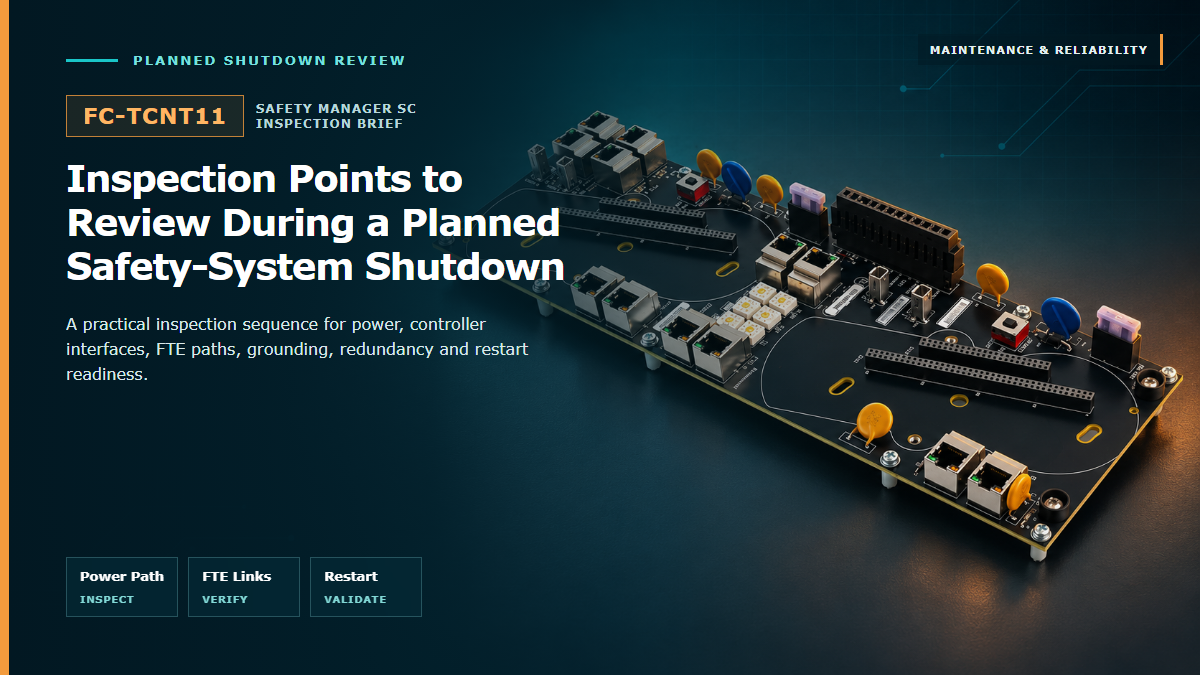
A planned outage creates a controlled window to inspect the Honeywell FC-TCNT11 redundant controller IOTA, verify the interfaces around it, and correct developing problems before the Safety Manager SC system returns to service.
The FC-TCNT11 is the controller IOTA used in the Honeywell Safety Manager SC architecture. It provides the physical interface for the safety controller modules, carries 24 VDC power from the cabinet bus bars, and provides the redundant communication paths used by the controller assembly. Its condition therefore affects power continuity, controller seating and network availability at the same time.
A shutdown inspection should treat the IOTA, its installed controller modules, the mounting arrangement, the power path and all connected communication cables as one assembly. A clean front surface or a healthy controller indication alone does not prove that the underlying connectors, fuse, grounding points or redundant links are ready for another operating cycle.
Before the cabinet is opened, capture the operating baseline. Record active diagnostics, controller status, synchronization state, FTE path condition, downlink health, cabinet temperature and any standing alarms. Confirm the installed controller models, their positions and the complete FC-TCNT11 identification so the post-maintenance state can be compared with a known starting point.
The work pack should also identify every approved bypass or inhibit, the latest verified controller application, the required proof-test scope, the expected communications after restart and the rollback point. This prevents a mechanical inspection from becoming an uncontrolled configuration change.
The FC-TCNT11 receives 24 VDC from the cabinet bus bars and transfers power to the controller modules. With the assembly safely isolated, inspect the bus-bar connection points, captive power fasteners, conductor condition and polarity identification. Look for looseness, damaged insulation, oxidation, contamination, discoloration or any sign that a joint has operated at an elevated temperature.
The power line includes an 800 mA type-F cylindrical fuse for short-circuit protection. A fuse should never be treated as a routine consumable: if it is open, heat-marked or has been replaced previously, determine the cause before energizing the system. Confirm that the replacement rating and type match the approved configuration.
The controller IOTA interfaces with the installed Safety Manager SC controller module through dual-row socket connections. After approved removal, inspect the mating areas for bent or recessed contacts, debris, moisture evidence, uneven wear and damage caused by misalignment. Check that guides, latches and mechanical supports are intact and that each controller can be seated without abnormal force.
Confirm that the installed controller modules are the approved models for the system release and that controller positions have not been exchanged without traceability. Label condition matters: a shutdown report should be able to identify the IOTA and each controller independently.
The FC-TCNT11 provides two Fault Tolerant Ethernet ports for the server-side redundant network and two Ethernet ports for controller downlinks. Inspect all four paths as paired services rather than as individual patch leads. Verify A/B identification, destination labels, connector retention, bend radius, strain relief and cable separation. Correct any crossed, unlabeled or unsupported cable before restart.
After reassembly, confirm that both redundant paths return to the expected state and that no port is carrying the entire communication load because its partner remained disconnected or degraded. Communication acceptance should include controller visibility, stable link indications and the absence of recurring network diagnostics.
Inspect the carrier and IOTA mounting points for secure fastening, distortion and evidence of vibration. Ground connections should be clean, mechanically sound and returned to the approved arrangement. Do not add unapproved washers, locking hardware or improvised supports that can interfere with the carrier or IOTA assembly.
Remove loose dust with an approved method and check for conductive contamination, corrosion, moisture tracks and blocked airflow. Review fan and filter condition, cabinet seals and surrounding cable routing. A recurring temperature or contamination problem should be corrected at the cabinet level rather than hidden by cleaning the IOTA alone.
A redundant controller assembly is not proven merely because two modules are installed. After power restoration, confirm that both controllers are recognized, synchronized and free of hardware or communication diagnostics. Compare the returned state with the pre-shutdown baseline and verify that the application and configuration identity are unchanged.
Any controller switchover, path-failure simulation or redundancy challenge must be performed only within an approved test plan. The acceptance criteria should define expected alarms, transition behavior, communication continuity and the conditions that require rollback.
Restore every connector, shield, ground and cable to its verified position. Remove temporary controls only through the site's bypass register, then confirm controller health, FTE redundancy, downlink communication, system time, alarm handling and all safety functions included in the shutdown scope. Do not close the work order while an unexplained diagnostic remains active.
The final record should identify what was inspected, what was disturbed, the condition found, corrective work completed, replacement part identities and the exact acceptance tests passed. Trend any heat, corrosion, connector wear or intermittent network issue so the next outage begins with evidence instead of memory.
| Observation | Why it matters | Required decision |
|---|---|---|
| Fuse open or heat-damaged | May indicate a short circuit, overload or poor power connection. | Find and correct the cause before fitting the approved fuse and energizing. |
| Bent, corroded or recessed contacts | Can compromise controller power or signal continuity. | Quarantine the affected hardware and obtain an engineering disposition. |
| Only one FTE path returns | The system may be operating without intended communication redundancy. | Trace the failed path and restore redundancy before release. |
| Controller identity or configuration mismatch | The installed assembly no longer matches the approved baseline. | Stop, verify the correct hardware and configuration, and apply change control. |
| Persistent hardware or synchronization diagnostic | Redundant operation has not been fully restored. | Do not declare the safety system available until the cause is resolved. |
A successful FC-TCNT11 inspection leaves a traceable baseline: the power path is sound, the controller interfaces are undamaged, both communication paths are healthy, the mechanical installation is secure and the redundant controller assembly has passed the site's approved return-to-service tests. That evidence is more valuable than a simple statement that the cabinet looked clean.
The following industrial automation models are available for sourcing inquiries. Confirm the complete model, revision, quantity and required condition before ordering.
| MOV-175 | IPSI-2 | AKM115F120 |
| K-6010 | Dba-ea43/A10rh | VCL-E1-030 |
| pdrc816FR-knx | SB-HVAC2-DN | MS-RA205 |
| X87-813 | AMN11-S1 | AM-200 |
| KPDL400 | IC-41S | TPNN0077 |
| RH390 | MCW-211-SM-LC15 | HNWG50086423-006 |
| E12-C92-451 | QBT2101-BK-BTK | MF1CTJ0056 |
| LR9502 | PP056TB1-113 | TS5810N |
| VIB-10B | LF1B-NC3P-2THWW2-1M | ETRSEQ.0003 |
| LV-125 | PTXE6A-M | Safety-MS2 |
| P5055M-EXT-0E | EZV516 | ADCDW3895TU |
| TTS-SD-LCD-B-1 | ITRR832-001 | EC17Z |
| DM01D01ACC | L5504RVF20 | SHO100-T |
Send the complete FC-TCNT11 identification, installed controller configuration, required condition, quantity and destination for a focused sourcing review.
| Sales manager | Jim Pei |
| [email protected] | |
| ZXH18020776782 | |
| Phone / WhatsApp | +86 18020776782 |
 EN