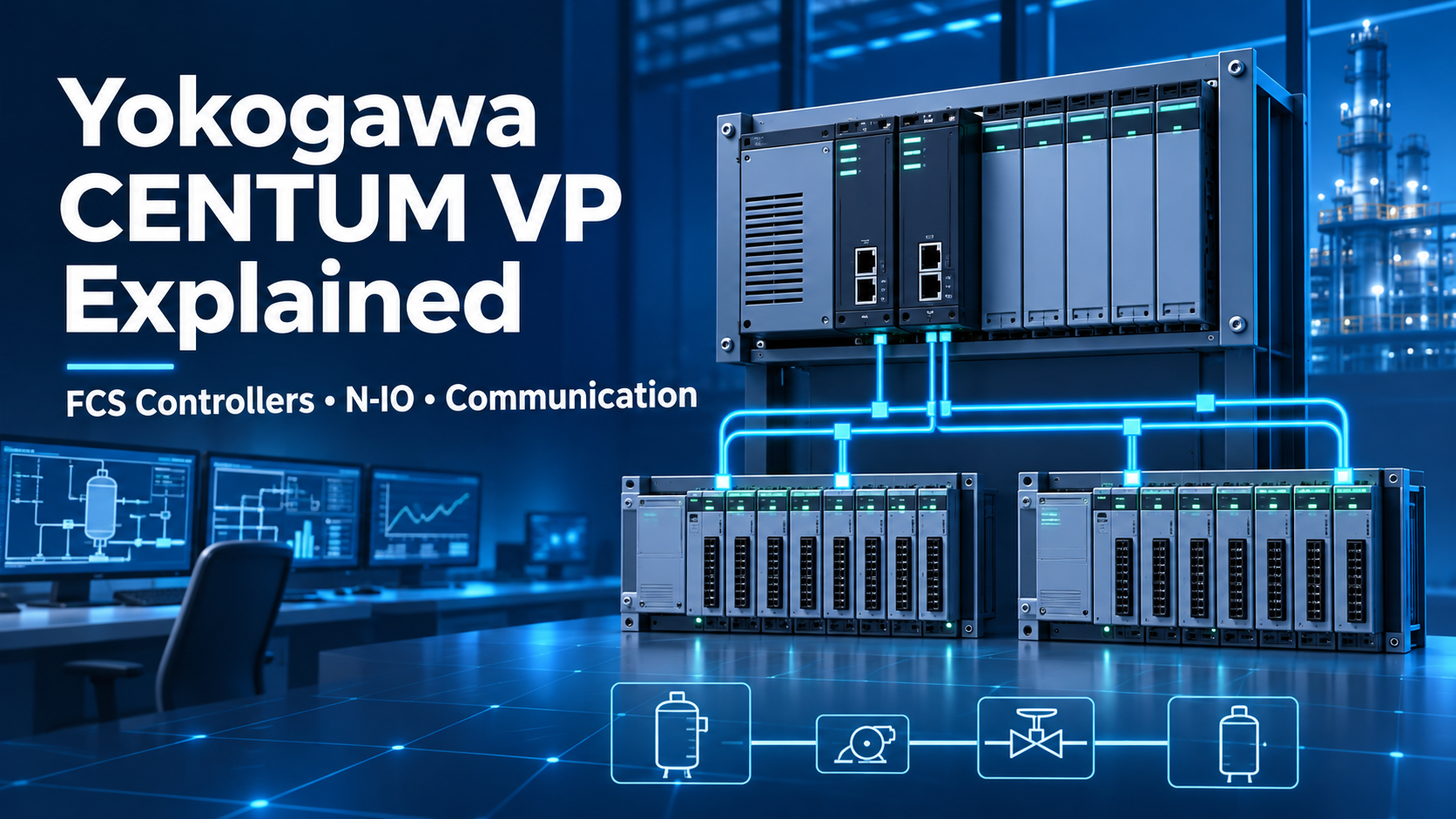
Yokogawa CENTUM VP brings the field control station, process I/O, operator environment and plant networks into one distributed control architecture.
Understanding how the FCS, N-IO and communication layers work together is essential when planning an expansion, replacing installed hardware or preparing a technically complete spare-parts inquiry.
CENTUM VP is Yokogawa's integrated production control system for continuous and batch process applications. At the control layer, a Field Control Station executes control functions and exchanges process data with the I/O subsystem. Human Interface Stations provide operator monitoring, while engineering and asset-management stations support configuration, diagnostics and lifecycle work.
The system can be designed for small or large installations and may include traditional FIO, software-configurable N-IO, digital field networks and third-party communication interfaces. The correct architecture depends on the installed CENTUM VP release, controller generation, redundancy design, hazardous-area requirements, field signal types and the existing network topology.
The Field Control Station is the real-time control layer of CENTUM VP. It receives field values, executes regulatory control, sequence logic and interlocks, and sends commands back to valves, drives and other final elements. Yokogawa's controller architecture supports redundant configurations for processors, power supplies, communication buses and related components where the selected system design permits.
| FCS Type | Typical Controller | Primary Role |
|---|---|---|
| FCS for N-IO | A2FV50S / A2FV50D | Connects N-IO nodes and selected FIO communication modules. |
| FCS for FIO | AFV30S / AFV30D and related configurations | Supports conventional Fieldnetwork I/O architecture. |
| FCS for RIO upgrade | A2FV70S / A2FV70D | Supports planned migration from selected legacy RIO installations. |
N-IO is Yokogawa's network I/O platform for CENTUM VP. Its architecture separates field termination from final channel assignment more flexibly than a traditional fixed-card design. An N-IO channel can be configured for supported analog input, analog output, digital input or digital output duties through engineering software and the appropriate I/O adaptor.
A typical N-IO node includes a node interface unit, a baseplate, I/O modules and signal adaptors or intrinsic-safety barriers. The A2NN30D node interface unit provides the interface between the controller-side bus and the N-IO I/O units. Models such as A2MMM843 and A2MDV843 provide the module layer, while adaptors including A2SAM105, A2SAM505, A2SAT105 and A2SDV105 define the required field-signal connection.
Communication in CENTUM VP is organized into distinct layers. Vnet/IP is the system's gigabit Ethernet-based control network. It uses dual-redundant Bus 1 and Bus 2 paths so that control communication can continue through the alternate path if the normal path becomes unavailable. HIS, engineering stations, FCS controllers and supported system servers exchange control and supervisory data across this network.
Between an FCS and N-IO nodes, the N-ESB bus or optical ESB connection provides the I/O communication path. Optical connections are useful when nodes must be installed remotely or electrical isolation is required. At plant-information level, standard Ethernet links CENTUM VP-related servers and clients to appropriate business or asset-management systems under the site's network and cybersecurity design.
CENTUM VP can also interface with field and subsystem networks including FOUNDATION Fieldbus, PROFIBUS-DP, Modbus RTU, Modbus TCP/IP and DeviceNet through supported communication hardware and software. Protocol availability must be verified against the exact controller, interface module, CENTUM VP release and third-party device profile.
Transmitters, switches and analyzers first connect to an appropriate I/O termination and signal adaptor. The I/O layer conditions the signal and passes data to the FCS. The controller executes the configured control strategy, then returns output commands through the I/O path. Operators monitor the process through the HIS, while engineering and maintenance personnel use authorized tools for configuration and diagnostics.
| Design Point | N-IO | FIO |
|---|---|---|
| Channel assignment | Software-configurable universal I/O with adaptors | Dedicated modules selected by signal type |
| Project changes | Flexible late binding can reduce rewiring | May require module and terminal changes |
| Best fit | New projects, flexible cabinets and phased expansion | Existing installations and established signal layouts |
| Selection priority | Baseplate, module, adaptor, redundancy and approvals | Module type, terminal board, isolation and channel count |
Before requesting CENTUM VP hardware, collect the following information:
The following models represent common CENTUM VP controller and N-IO hardware families. They are not universal substitutes. Compatibility must be confirmed from the complete system configuration and current Yokogawa documentation.
| Model | Hardware Type | Key Check Before Ordering |
|---|---|---|
| A2FV50S / A2FV50D | FCU for N-IO | Single/duplex form, release, licenses and node capacity |
| A2FV70S / A2FV70D | FCU for RIO upgrade | Legacy system, migration scope and release support |
| A2EN40S / A2EN40D | N-ESB bus coupler | Bus topology, redundancy and optical/electrical connection |
| A2NN30D | N-IO node interface unit | Mounting, power modules, environment and node design |
| A2BN3D | N-IO baseplate | Terminal type, adaptor selection and approvals |
| A2MMM843 | 16-channel analog/digital I/O module | Single or redundant module pair and compatible baseplate |
| A2MDV843 | 16-channel digital I/O module | Signal type, redundancy and baseplate support |
| A2SAM105 | Current/voltage input adaptor | Input range, transmitter wiring and HART requirement |
| A2SAM505 | Current/voltage output adaptor | Output range, load and field power |
| A2SAT105 | mV/thermocouple/RTD input adaptor | Sensor type, compensation and wiring |
| A2SDV105 | 24 VDC digital input adaptor | Voltage input or dry contact and field wiring |
| A2SDV505 | 24 VDC digital output adaptor | Load current, protection and power supply |
Send the complete nameplate photo, model and suffix codes, CENTUM VP release, quantity, required condition and destination. Our team will check stock information, product photos and ordering details before quotation.
CENTUM VP, N-IO and related product names are trademarks of their respective owners and are used for identification and informational purposes only. Compatibility, installation, configuration and safety decisions should be reviewed by qualified personnel using current manufacturer documentation and the site's approved procedures.
 EN