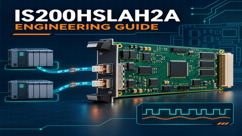
The IS200HSLAH2A is the HSLA high-speed serial-link interface board used within the GE EX2100e excitation-control architecture. Its job is narrow but important: it supports the fast internal communication path between a host controller and associated interface hardware. Correct identification, system matching and disciplined replacement practice matter more than treating it as a generic communication card.
Match the complete IS200HSLAH2A marking, the installed host assembly and the project bill of materials. HSLA identifies the board family, but the shared family name does not prove that another suffix is a drop-in replacement.
The GE abbreviation HSLA means High-speed Serial Link Interface Board for Host Application Boards. In the EX2100e regulator system, interface boards are interconnected through a high-speed serial link (HSSL) and connect onward to their associated I/O terminal hardware. The IS200HSLAH2A therefore belongs to the internal control-communication layer rather than the field terminal layer.
That distinction is useful during troubleshooting. The board is not an Ethernet switch, an analog-input terminal board or a power-conversion module. Its value is in maintaining the deterministic data path expected by the host application hardware inside the excitation-control assembly.
GE's EX2100e dual-control block diagram shows HSLA connections in the M1 and M2 control paths, including the UCSB controllers and ERAX interface hardware, with other system boards such as ESYS and EDFF participating in the wider control arrangement. This architecture supports the regulator's separation between controller processing, interface functions and power-conversion equipment.
Engineers should also separate HSSL from the plant-level networks around it. EX2100e systems may use Ethernet, EGD, Modbus Ethernet, UDH or IONet elsewhere in the architecture. An HSSL fault must not be diagnosed as an Ethernet fault simply because both involve communication.
IS200HSLAH2A is the complete identity to use for procurement and maintenance. Do not shorten it to IS200HSLA, and do not assume that a board carrying a different group or revision suffix is interchangeable. The host-board pairing, link arrangement, control revision and project configuration must all be confirmed against the installed equipment records.
| Check | Why it matters |
|---|---|
| Complete board code | Confirms the exact HSLA variant and revision being replaced. |
| Host assembly | Prevents fitting a board that does not match the installed controller hardware. |
| Cable and link records | Preserves the original HSSL routing and channel assignment. |
| Project BOM and drawings | Provides the safest basis for an engineering replacement decision. |
Loss of internal communication, repeated controller-interface alarms, an interface board that is not recognized, or unstable data exchange can place the HSLA path on the troubleshooting list. These symptoms do not prove the IS200HSLAH2A itself has failed. A loose connector, damaged cable, incorrect replacement, host-board problem, control-power issue or configuration mismatch can produce similar results.
Board work should be performed under the site's approved shutdown, isolation and electrostatic-discharge procedures. Before removal, photograph the board location, label each cable, record the complete nameplate and capture the relevant controller diagnostics. Protect the connectors and circuit board from static discharge, contamination and mechanical stress.
The EX2100e warm-backup architecture can use independent M1 and M2 controls with separate controllers and power-conversion paths. The wider system is designed to support transfer between active and backup functions, but an HSLA intervention still requires careful channel identification. Engineers must know which control path is active, which path is being serviced and how the installed configuration handles a link or controller fault.
After replacement, verify that the controller recognizes the associated interface hardware, communication alarms clear, expected channels report correctly and the active/backup state matches the operating procedure. Return the excitation system to automatic service only after the plant's approved functional checks are complete.
GE's EX2100e product description defines HSLA, shows the HSSL architecture and explains the regulator's controller, interface and warm-backup structure.
Open the GE Vernova EX2100e product description| HG659b | FP2011-U1 | DDRC810 |
| BZMB1-A32-BT | VE3A11701 | PDMMPR-303-1 |
| SOV680135 | 2938730 MINI-PS-100-240AC/24DC/2 | 181B0729 SPR-CMB21640 |
| SEL-9321 932160X | MSP750.431 | ABB 8300-0-8042 M251021P4 |
| B&R ECI164-0 | 773-10 10dB | BEPM-OC |
| DR4019006 | 2CDG110235R0011 | 311025A |
| TM3DI8 | BMXCPS2000 | QND-6082R |
| 2CDG 110 153 R0011 | BC-GT30 | PXC100.D |
| AP-ANT-40 JW017A | AES75-12 | 34.51.7.024.0010 |
| LIOB-452 | SF61B 1025AV01, SF61-APK-S001 | CP-8800-A-KEM |
| CT/LCFP-BR/GLD 6001990 | 01-ELITEEXEC4 | D-67722, MX-SM-N160-LPF-PW |
| 46904 KHA6-SH-Ex1 | 3HE05833CAAA01 XFP-10GE IPU3AT9JAA | GE IC699APU300HRA |
| ABB UMC100 1SAJ530000R1210 | 4825-0094 2IN/2OUT | 440E-A17112 |
| PCS090 PG090.204.A | 2CDG110167R0011 | 6GK5991-1AF00-8AA0 |
 EN