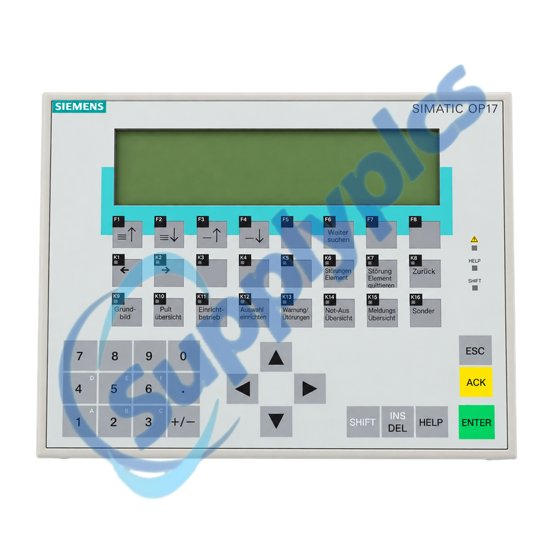
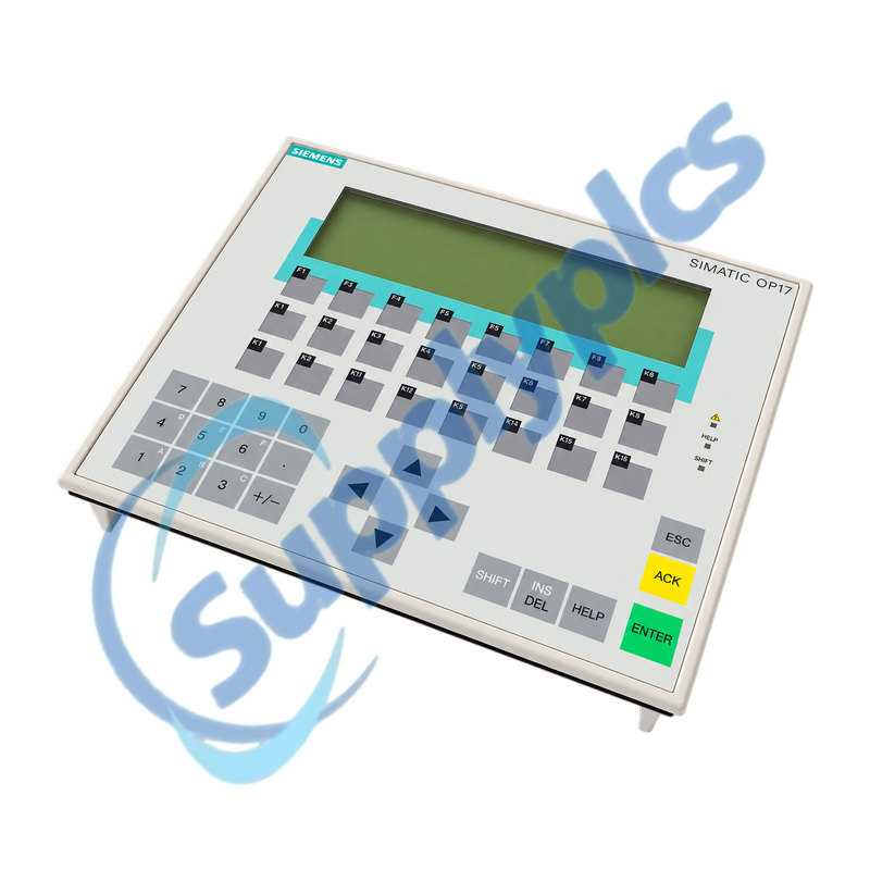
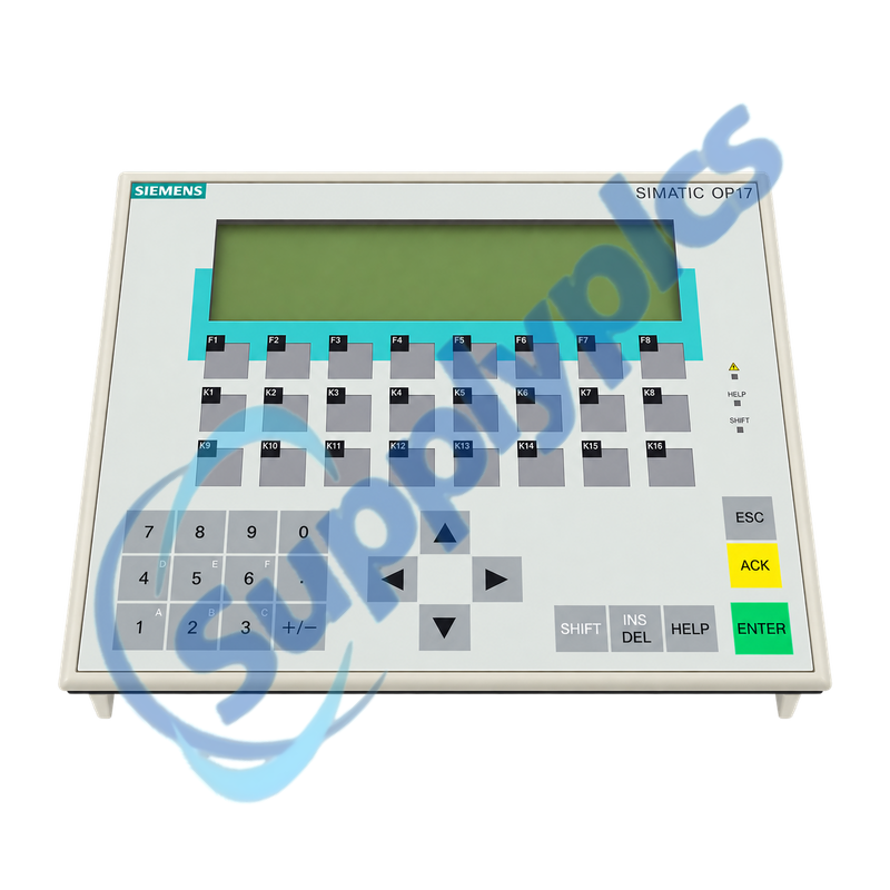
Text-based operator panel with configurable function keys and MPI or PROFIBUS communication
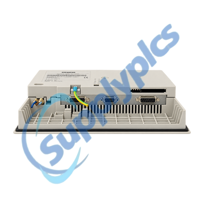
The OP17-PP combines a monochrome STN text display, membrane keyboard, function-key LEDs and configurable PLC and printer interfaces. Replacement depends on the editable ProTool project, the selected IF1A or IF1B communication path, the transfer connection and the existing panel cutout.
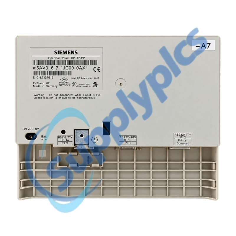
Panel migration recordSecure the editable ProTool project and record the complete rear label, interface assignment, PLC address and baud rate, printer or download cable, 24 V DC supply, cutout and grounding before the installed panel is disconnected.
Project Transfer
6AV3617-1JC00-0AX1 is the SIMATIC OP17-PP operator panel for machine operation and message display. Its rear connections provide IF1A for RS232 or TTY communication, IF1B for RS422 or RS485 PLC communication and IF2 for RS232 or TTY printer and download functions.
Service success depends heavily on project availability. A visual copy of the screens is not a substitute for the editable ProTool project, configured PLC driver, addresses, recipes and alarm texts. These assets should be recovered before a failed display or communication channel makes transfer impossible.
Protect the editable HMI project and the correct transfer route before a legacy panel is taken out of service.
Editable source
Archive the ProTool project, text lists, recipes and alarm definitions; a backup image alone may not support later screen changes.
Download path
Record the IF2 cable, PC adapter, transfer settings and panel transfer mode that successfully communicates with the installed unit.
Driver settings
Save the selected PLC driver, station address, baud rate and any network-specific parameters together with the project version.zai
Panel Integration
Mechanical fit, supply quality and interface selection must agree with the original machine design.
PLC interface
Use IF1A for the configured RS232 or TTY path or IF1B for the configured RS422 or RS485 path; these ports are not interchangeable without project and cable changes.
Printer interface
Keep IF2 printer or download use separate from the PLC connection and reproduce the original pinout and transfer workflow.
Cabinet fit
Confirm the 231 x 195 mm cutout, rear clearance, seal condition, protective earth and stable 24 V DC supply before commissioning.
How can an engineer confirm that 6AV3617-1JC00-0AX1 is the PP interface version required by the machine?
Match the complete rear label and check the IF1A, IF1B and IF2 markings. Compare the configured PLC driver and cable with the installed RS232 or TTY, RS422 or RS485 and printer or download connections.
Q2
What should be recovered from 6AV3617-1JC00-0AX1 before the display or keyboard fails completely?
Recover the editable ProTool project, recipes, alarm texts and transfer settings while communication is still possible. Also photograph every screen and record the PLC driver, address, baud rate, language set and working download cable.
Q3
Why might 6AV3617-1JC00-0AX1 enter transfer mode but fail to accept a project?
An unsuitable IF2 cable, PC adapter, baud rate or transfer setting can prevent the session from starting. Match the original transfer path and ProTool environment, then confirm that the panel is in the intended transfer mode before retrying.
Q4
How should a technician diagnose lost PLC communication on 6AV3617-1JC00-0AX1?
Identify whether the project uses IF1A or IF1B, then check the corresponding cable, termination, station address and baud rate. Use the panel communication message and PLC-side status to separate a wiring problem from a project-driver mismatch.
Q5
What installation details matter when 6AV3617-1JC00-0AX1 is fitted into an existing cabinet door?
Confirm the 231 x 195 mm cutout, mounting depth, sealing surface and rear ventilation. Reproduce the protective-earth and 24 V DC connections and inspect the front seal so the original IP65 front protection is not compromised.
Q6
What evidence should a buyer provide when requesting a replacement for 6AV3617-1JC00-0AX1?
Provide the full rear-label photograph, front-panel layout, interface and cable photographs, supply voltage and the ProTool project or version information. Include whether IF2 is used for a printer, download or both in the established service procedure.
 EN