Get a Free Quote

Our representative will contact you soon.
Email
Name
Mobile
Company Name
Message
0/1000
allen bradley controllogix 1756 1756 rm2 redundancy enhanced module original new-0

Allen Bradley ContrlLogix

Home >  Products >  ROCKWELL >  Allen Bradley ContrlLogix

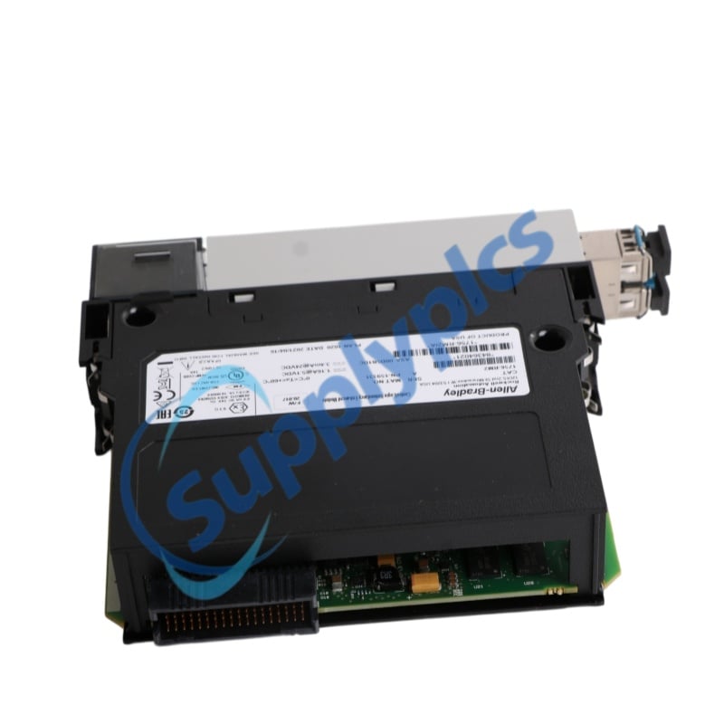
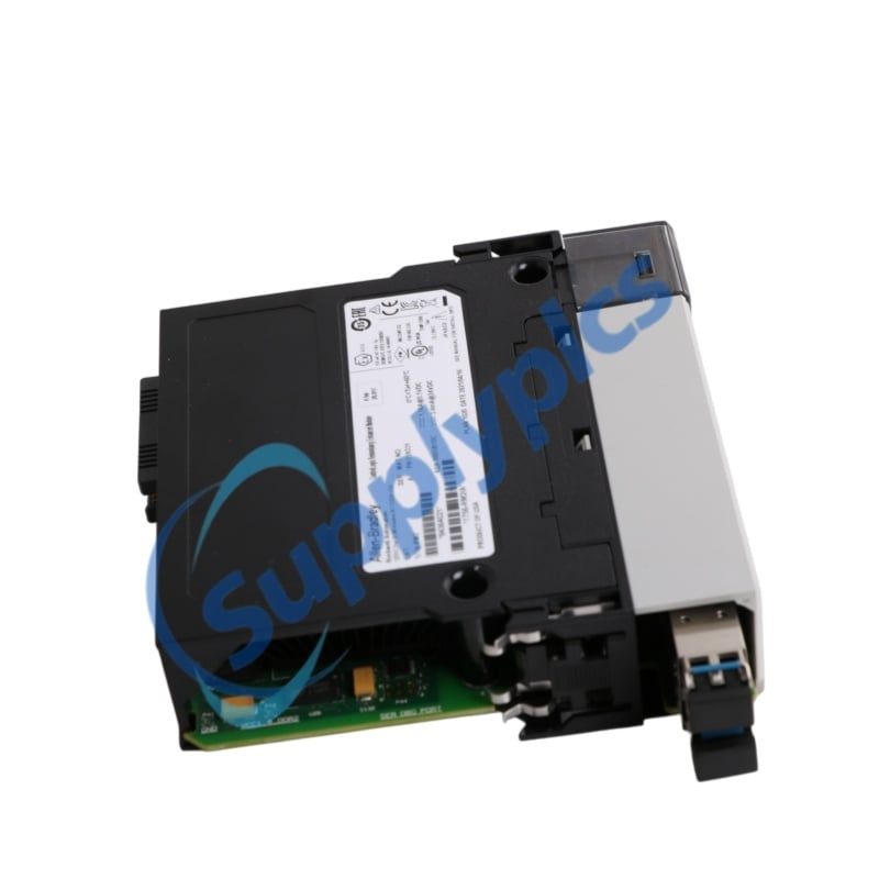
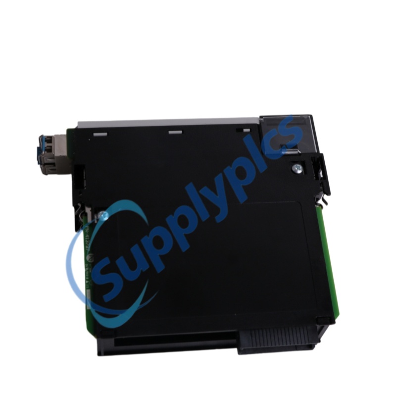
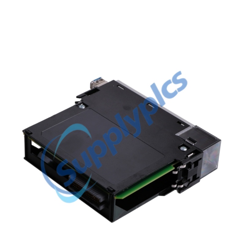
Allen-Bradley ControlLogix 1756 1756-RM2 Redundancy Enhanced Module | Original New

Allen-Bradley ControlLogix 1756 Redundancy Enhanced Module
Complete Model
1756-RM2
Official Product Description
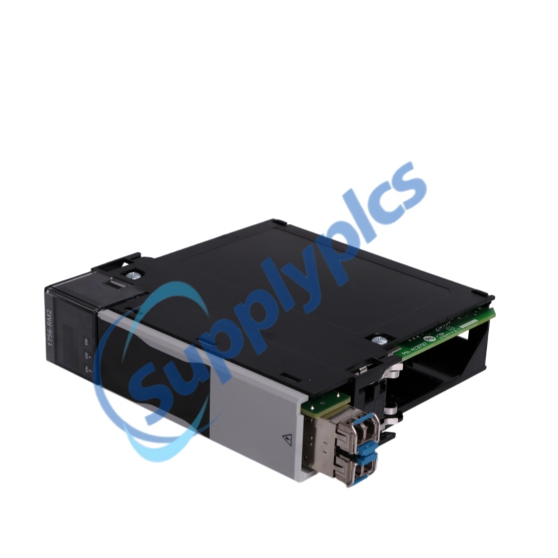
Allen-Bradley 1756-RM2 ControlLogix enhanced redundancy module with two fiber-optic channels, 1000 Mbps operation and support for ControlLogix 5570 and 5580 redundancy systems.
CORE FEATURE: Dual 1000 Mbps fiber-optic redundancy channels for synchronized ControlLogix chassis pairs.
LEAD TIME: In stock
WARRANTY: 1 year
Appurtenance:
  • Overview
  • Technical Data
  • Inquiry
  • Features
  • Interfaces
  • Installation
  • Environment
  • FAQ
  • Recommend Models
  • Recommended Products
Product Overview
1756-RM2 is an Allen-Bradley ControlLogix enhanced redundancy module for synchronized primary and secondary ControlLogix chassis.
Rockwell Automation specifies two fiber-optic channels, 1000 Mbps operation and compatible singlemode 1756-RMC1, 1756-RMC3 and 1756-RMC10 redundancy cables.
The module occupies one slot in a standard ControlLogix chassis and supports ControlLogix 5570 and ControlLogix 5580 controller families within validated redundancy system combinations.

Technical Data

Complete model
1756-RM2
Brand
Allen-Bradley / Rockwell Automation
Product family
ControlLogix 1756
Product type
Enhanced redundancy module
Lifecycle status
Active Mature
Redundancy channels
2 fiber-optic channels
Signal type
Fiber optic input and output
Channel rate
1000 Mbps
Connector cables
1756-RMC1, 1 m; 1756-RMC3, 3 m; 1756-RMC10, 10 m
Current draw at 5.1 VDC
1.16 A
Current draw at 24 VDC
3.4 mA
Power dissipation
6 W maximum
Thermal dissipation
21 BTU/hr
Dimensions
Numeric dimensions are not stated in official publication 1756-TD001W; standard ControlLogix single-slot module
Weight
Approximately 0.29 kg (0.64 lb)
Slot width
One ControlLogix chassis slot
Module location
Chassis-based, any slot
Compatible chassis
1756-A4, 1756-A7, 1756-A10, 1756-A13 and 1756-A17
Supported controller families
ControlLogix 5570 and ControlLogix 5580
Standard power supplies
1756-PA72, 1756-PA75, 1756-PB72 and 1756-PB75
Redundant power supplies
1756-PA75R, 1756-PB75R and 1756-PSCA2
Enclosure type
None, open-style equipment
Temperature code
T4
Operating temperature
0 to 60 degrees C
Storage temperature
-40 to +85 degrees C
Relative humidity
5 to 95 percent, noncondensing
Certifications
CE, RCM, cULus, ATEX, IECEx, UKEx, UKCA, FM, KC and CCC when marked
Official sources
Rockwell Automation 1756-RM2 product page; publication 1756-TD001W-EN-P pages 87 to 89; publication 1756-IN087C-EN-P pages 5 to 9

Inquiry

Features

Enhanced redundancy
The module synchronizes matched primary and secondary ControlLogix chassis for high-availability control.
Dual fiber channels
Two redundancy channels allow a second fiber link to be installed for fiber-path redundancy.
Gigabit link rate
Rockwell Automation specifies 1000 Mbps for the redundancy channels.
Controller-family support
The official technical data lists ControlLogix 5570 and ControlLogix 5580 controller families.

Interfaces

Channel 1
Connect a compatible singlemode 1756-RMC fiber-optic cable between the matched redundancy modules.
Channel 2
Install an optional second compatible fiber-optic cable to provide redundant fiber media.
Supported cables
Use 1756-RMC1, 1756-RMC3 or 1756-RMC10 according to the required chassis separation.
Backplane interface
Install the module in one slot of a standard ControlLogix chassis and include 1.16 A at 5.1 VDC in the power budget.

Installation

01 - Verify the exact catalog number
Match 1756-RM2 on both modules, quotations, labels, packaging and Rockwell Automation product records.
02 - Match both chassis
The primary and secondary chassis must use matching components, slot positions, controller families and compatible firmware.
03 - Install the module pair
Insert one 1756-RM2 in each standard ControlLogix chassis in the same slot position.
04 - Connect fiber channels
Connect an approved 1756-RMC cable to channel 1 and, when required, a second approved cable to channel 2.
05 - Qualify the redundancy system
Verify firmware, RMCT compatibility, chassis synchronization and qualified redundancy status before service.

Environment

Operating temperature
0 to 60 degrees C.
Storage temperature
-40 to +85 degrees C.
Relative humidity
5 to 95 percent, noncondensing.
Protection
Open-style equipment; install it in a suitable industrial enclosure.
Laser safety
The fiber-optic system is a Class 1 laser product; installation and service must follow the official safety instructions.
System matching
The components in the primary and secondary chassis must match for the redundancy system to synchronize.

FAQ

Q1. How can the exact quoted 1756-RM2 be verified?
Match 1756-RM2 on the quotation, both module labels and packaging. Confirm two fiber channels, the standard ControlLogix chassis version, 0 to 60 degree C rating and one-slot format.
Q2. How can New, Used or Refurbished condition be distinguished?
Request date-marked photos of the full label, serial and series markings, both fiber channels, SFP areas, indicators, backplane connector and housing. Check for fiber-port contamination, latch wear, altered labels and previous chassis marks.
Q3. How should supplier legality and reliability be checked?
Verify the supplier legal entity, registered address, invoice details, payment beneficiary and traceable contact. The offer must identify Allen-Bradley 1756-RM2, condition, series, quantity and included 1756-RMC cables.
Q4. Which specifications must engineering confirm before purchase?
Confirm both chassis configurations, controller family, firmware bundle, RMCT version, slot positions, 1000 Mbps fiber channels, 1756-RMC cable length, backplane power and system certifications.
Q5. What physical evidence should be requested before payment?
Ask for one date-marked photo set showing both 1756-RM2 labels, serial and series markings, channel 1 and channel 2 ports, status indicators, backplane connectors, seals, packaging and included fiber cables.
Q6. Can 1756-RM2XT or 1756-RM3 replace 1756-RM2?
Not automatically. 1756-RM2XT requires an XT chassis and power supply and has an extended temperature range, while 1756-RM3 migration requires validated firmware and system architecture. Confirm the complete redundancy system before substitution.

Recommend Models

AF1-B0-34-615-1G1-C
Ti300
NJ2-6.5-40-E2
VFS4500-5FZ
Scp461-51
WMZH2D20
3458A
JA1-A8-A
3000-16x125L
GV2LE16
A-13543-002
NPC-II-3U-DB9
CC-100E
RT4A4L24
NR-2012-PM
ABB PM866A 3BSE076359R1
IC693ALG390C
592-B0V16
46MT40F
8320B177
IIT232
7121KBN1NF00
A03B-0807-C011 AIF01A
VUVG-LK14-M52-AT-G18-1H2L-S
032F1204
XC01302KGDFL24-TK
TL-M2ME2
1C19657P1S
D26MB
VIB5.600
k16175
DAP218/AS-BDAP-218
GE YSILS1B IS220YSILS1BB
4XHBU-SS
KCP5 871301
E39-F32B5
DRTS-6
L90T03HKHF8LH6DLXXNXXS67U67W2J
ABB REB650 1MRK006520-AD
GALAXY816
A13-EB03M
01-982.3
800T-A6D2
ABB NBMNAAABNEC1BNN1XF
86500-2
N6705C
KSG-4312-K30-6K-KEP3-KM-3BC-24VDC
OAW6 20-8 H12
H8BM-RB
BC-ATS-151510
LC1D098BD
82A-0A-BRA
MSP10P
Is200tbtch1b
TLS0406
44B-AAA-GDDA-1KB
DBL175 1SNL317510R0000
SIEN-M8B-PO-KL
1771-ID
IC693MDL330G

Get a Free Quote

Our representative will contact you soon.
Email
Name
Mobile
Company Name
Message
0/1000

Get a Free Quote

Our representative will contact you soon.
Email
Name
Mobile
Company Name
Message
0/1000