Get a Free Quote

Our representative will contact you soon.
Email
Name
Mobile
Company Name
Message
0/1000
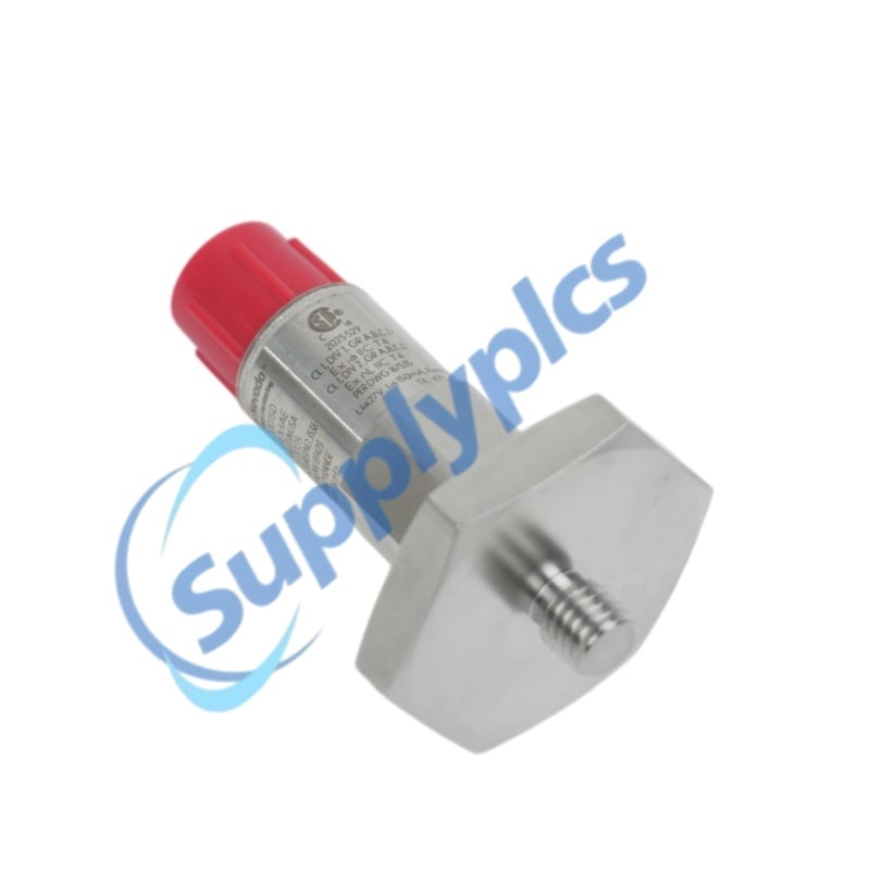
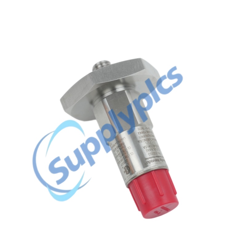
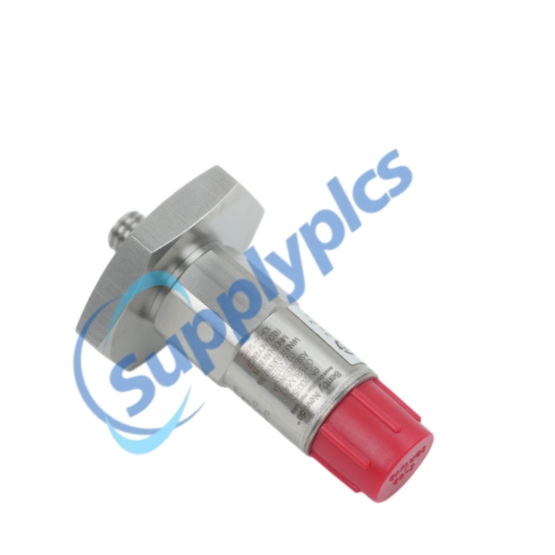
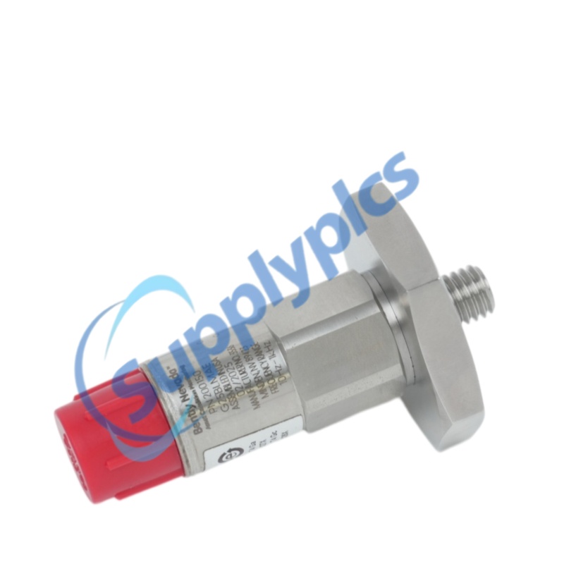
bently nevada 20015x 200151 40 03 02 accelerometer interface armored cable-0

Bently Nevada Cables

Home >  Products >  BENTLY NEVADA >  Bently Nevada Cables

Bently Nevada 20015x 200151-40-03-02 Accelerometer Interface Armored Cable

BENTLY NEVADA | 20015X ACCELEROMETER ACCESSORIES
200151-40-03-02
Accelerometer Interface Standard Cable with connectors on both ends
CONFIGURATION: 4.0 m cable length | Blue cable with armor | Nylon coupling nuts | Connectors on both ends
LEAD TIME: In stock
WARRANTY: 1 year
Appurtenance:
  • Overview
  • Technical Data
  • Inquiry
  • Construction
  • Installation
  • Selection Guide
  • Environment
  • FAQ
  • Recommend Models
  • Recommended Products
Bently Nevada 200151 Accelerometer Interface Cable
Exact configured model: 200151-40-03-02
Official product identity
The 200151 is the standard accelerometer interface cable for the Bently Nevada 20015x accelerometer family. It uses connectors on both ends and carries the transducer signal between the accelerometer and compatible monitoring hardware.
Configured geometry
Option A:40 specifies a 4.0 meter cable. The official cable data lists a 63.5 mm minimum bend radius for the 200151 construction.
Connection package
Option B:03 specifies blue cable with armor. Option C:02 specifies nylon coupling nuts; the 200151 cable has connectors on both ends.
Installation focus
Route the 4.0 m cable without violating the 63.5 mm minimum bend radius, protect it from sharp edges, and fully seat both nylon coupling nuts on the correct mating connectors.
Procurement check
Match every segment of 200151-40-03-02. The A, B and C suffixes define length, armor and coupling-nut material. A quotation must match 40, 03 and 02 exactly.

Technical Data

Official configuration and specifications
Complete model
200151-40-03-02
Product family
Bently Nevada 20015x Accelerometer Accessories
Product type
Accelerometer interface standard cable, connectors on both ends
Cable length
4.0 m (option 40)
Armor
Blue cable with armor (option 03)
Coupling nuts
Nylon coupling nuts (option 02)
Construction
4-conductor, 22 AWG; braided shield and drain wire with at least 85% coverage; PVC outer jacket
Connector configuration
Molded connectors on both ends
Minimum bend radius
63.5 mm (2.5 in) for 200151 cable
Maximum family cable length
25 m (82 ft)
Cable operating temperature
-20 to +100 °C (-4 to +212 °F)
Seal at mating hardware
IP67 when connected to the transducer and mating hardware
Dimensions
4.0 m specified cable length; 63.5 mm minimum bend radius
Weight
Not stated in Datasheet 164986 Rev. Y
Official document
Datasheet 164986 Rev. Y, pages 4 and 8

Construction

Signal cable core
Four 22 AWG conductors carry the accelerometer interface signals.
Shielding
A braided shield and drain wire provide at least 85% coverage.
Armored jacket
Suffix 03 identifies the blue armored construction for mechanical protection.
Connector package
Molded connectors are fitted on both ends and suffix 02 selects nylon coupling nuts.

Installation

Cable routing
Route the 4.0 m assembly away from sharp edges and moving components.
Bend control
Maintain at least the official 63.5 mm minimum bend radius.
Connector seating
Align the mating connectors before tightening the nylon coupling nuts; do not force the threads.
Low-temperature handling
Prevent flexing or bending below -20 °C because the official datasheet warns that cold flexing can damage the cable.

Selection Guide

200151
Accelerometer interface standard cable with connectors on both ends.
40 | Length
4.0 meter cable.
03 | Armor
Blue cable with armor.
02 | Coupling nut
Nylon coupling nut.
Seal
Connected hardware provides an IP67 seal.
Temperature
Cable operating range is -20 to +100 °C.
Compatibility check
Verify both mating connectors and the connected 20015x accelerometer/monitoring channel before ordering.

Environment

Temperature
The cable operating range is -20 to +100 °C.
Moisture protection
Molded connectors provide an IP67 seal when correctly mated to the transducer and hardware.
Mechanical handling
Respect the 63.5 mm minimum bend radius and avoid crushing or twisting the armored cable.
Inspection
Check the armor, PVC jacket, connector molding and nylon coupling nuts for damage before installation.

FAQ

Q1. How do I verify that the quotation is for the exact cable?
Require 200151-40-03-02 on the quotation and label. Confirm a 4.0 m 200151 cable, blue armor, nylon coupling nuts and connectors on both ends.
Q2. How can New, Used and Refurbished condition be distinguished?
Request current close-up photographs of both molded connectors, both nylon coupling nuts, the complete 4.0 m armored jacket and the identification label. Look for thread wear, cuts, repairs, crushing or altered markings.
Q3. How can the supplier be checked for legitimacy and reliability?
Verify the legal company name, registration, address, bank beneficiary and traceable contacts. Compare the exact suffix against Bently Nevada Datasheet 164986 Rev. Y and require exact-model evidence.
Q4. Which specifications must an engineer confirm before purchase?
Confirm cable length, armor, coupling-nut type, mating connector compatibility, 63.5 mm minimum bend radius, -20 to +100 °C cable range and the required 20015x system connection.
Q5. What physical evidence should be requested before payment?
Ask for dated photographs or video showing the complete label, both connector ends, nylon coupling nuts, uninterrupted armored jacket and a length measurement for the 4.0 m assembly.
Q6. Can another 200151 suffix or a 200152 cable replace it?
Not automatically. A changes length, B changes armor and C changes coupling nuts. The 200152 has a connector on the accelerometer end only, so it is not equivalent to this connectors-on-both-ends cable.

Recommend Models

60 randomly selected industrial automation models
FC-UGAO01
KJ3241X1-EA1
80190-480-01-R
DS200SDCCG1A
8EI2X2HWD10.0600-1
Edge Controller IC695CPL410
Siemens 6ES7513-1RL00-0AB0
EPRO MMS6312
2707-V40P2N
IC693MDL742
22B-D6P0N104
ProSoft PLX31-PND-MBS4
IC695CPU315
RH928CY
80190-220-01-R
CMC16 200-530-022-014
IMDSO14
Emerson A6120
X20SI4100
PM554-TP-ETH
MVME61006E-0161
T8461C
X20CP0483
F3316
A 5X00419G02 Ethernet Link Controller
ProSoft MVI69E-MBS
IEMMU01
KDA3.3-100-3-A00-W1
3HAC058993-004
F3 DIO 20/8 02
VME162PA-344SE
B 1C31181G02 Remote I/O Module
Yokogawa ADV151-E60/D5A00
16 ACS580-01-206A-4
IOCN 200-566-101-012
CC-PDIH01
Yokogawa AAI143-H50/K4A00
3HAC023020-003
TRICONEX 8312
X-CPU 01
2711R-T4T
Tricon 3008
DS3800NDAC1B1C
EPRO MMS6310
TRICONEX 3703E
Yokogawa S2MMM843-SS1130
160-BA04NSF1
MVME167-032A
1761-L32BWA
Yokogawa AAI543-S50/K4A00
2711R-T10T
3HAC058612-00
Emerson A6312
MVME147-012
ProSoft PLX51-DNPS
INIIT13
80190-100-01-R
T8850C
2715P-T10CD
TRICONEX 3636R

Get a Free Quote

Our representative will contact you soon.
Email
Name
Mobile
Company Name
Message
0/1000

Get a Free Quote

Our representative will contact you soon.
Email
Name
Mobile
Company Name
Message
0/1000