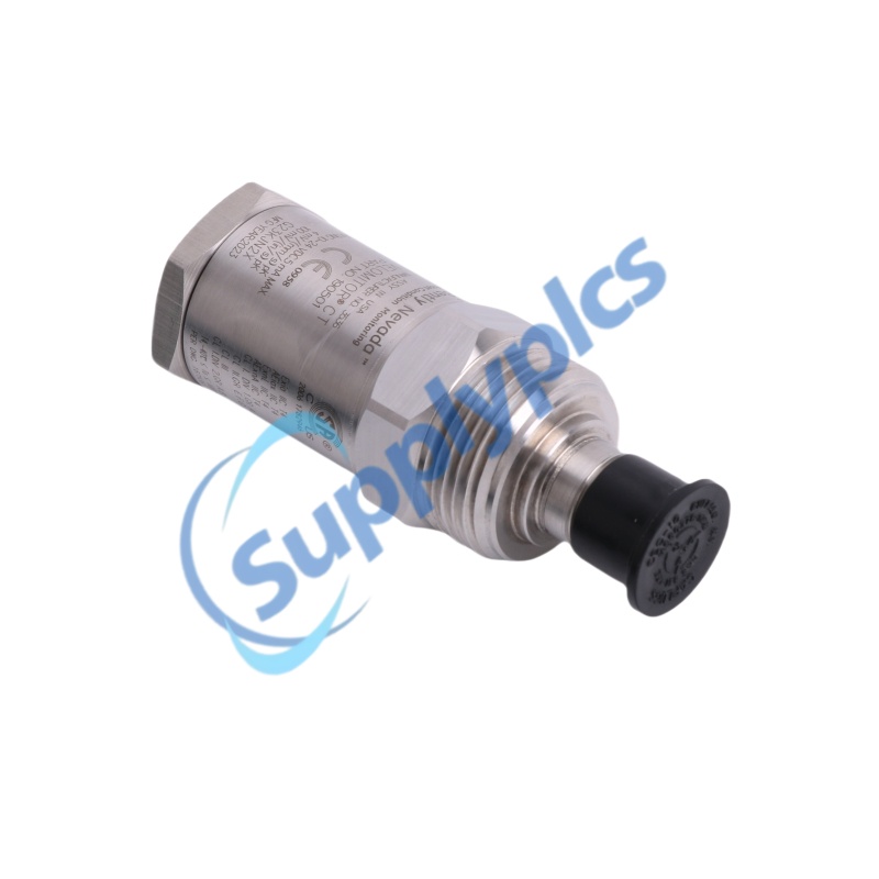
|
BENTLY NEVADA | VELOMITOR CT
190501-12-00-04
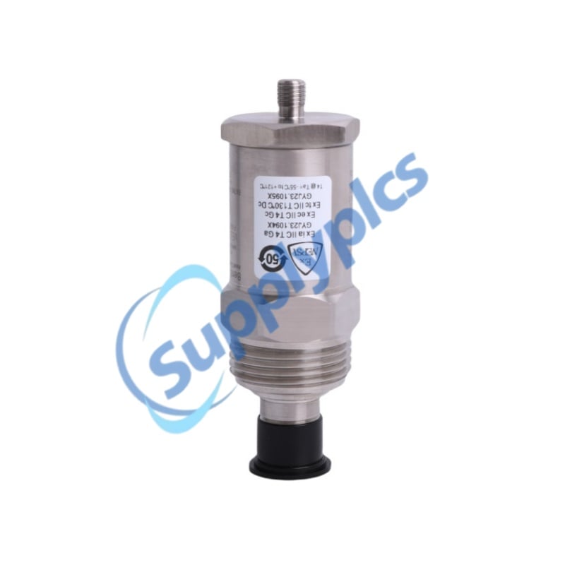
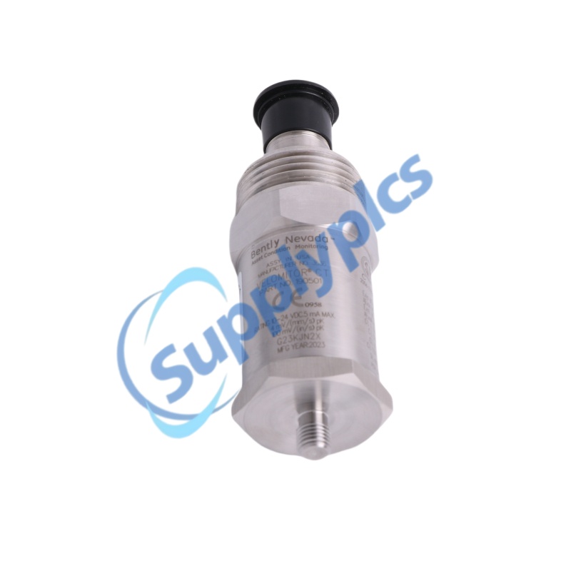
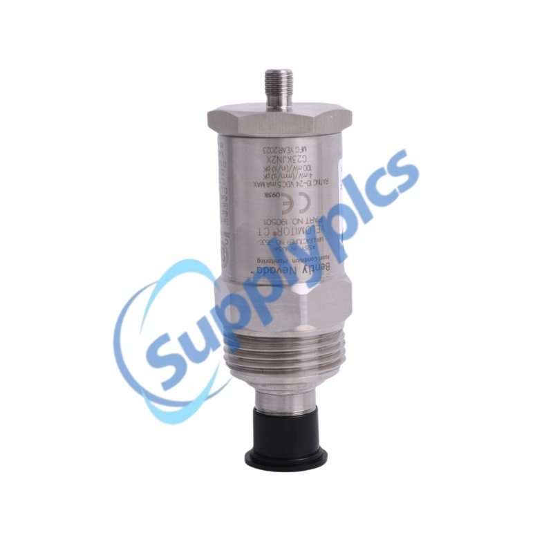
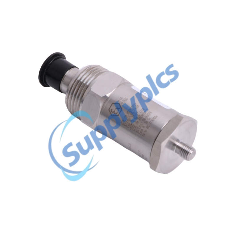
Velomitor CT Velocity Transducer
M8 x 1 plate stud | MIL-C-5015 interface | CSA, ATEX and IECEx approval option
|

Bently Nevada 190501-12-00-04
The 190501-12-00-04 is a Velomitor CT low-frequency velocity transducer for cooling-tower and air-cooled heat-exchanger fan machinery operating at or above 90 rpm. Code 12 specifies a 3/8-24 to M8 x 1 plate stud, code 00 specifies the MIL-C-5015 connection interface, and code 04 specifies the CSA Class I Division 1 plus ATEX, IECEx and CSA Class I Zone 0/1 approval option.
Core value: low-frequency integrated velocity measurement with a rugged stainless-steel case and hazardous-area approval option.
|
|
OFFICIAL SPECIFICATIONS | 190501-12-00-04
|
|
|
Complete model
|
190501-12-00-04
|
|
Product family
|
Velomitor CT Velocity Transducer
|
|
Product type
|
Low-frequency integrated piezoelectric velocity sensor
|
|
Dimensions
|
82 mm height; 33 mm mounting surface diameter; 35.6 mm maximum body diameter
|
|
Weight
|
Less than 297 g (10.5 oz), typical
|
|
Ordering option 12
|
Plate stud, 3/8-24 transducer thread to M8 x 1 machine connection
|
|
Connection option 00
|
MIL-C-5015 connection interface
|
|
Approval option 04
|
CSA Class I Division 1; ATEX, IECEx and CSA Class I Zone 0/1
|
|
Measurement application
|
Cooling-tower and air-cooled heat-exchanger fan machinery at or above 90 rpm
|
|
Measurement output
|
Velocity-proportional dynamic voltage output
|
|
Sensitivity
|
3.94 mV/mm/s (100 mV/in/s) +/-5%
|
|
Velocity range
|
63.5 mm/s peak (2.5 in/s peak)
|
|
Frequency response
|
3.0 to 900 Hz, +/-1 dB
|
|
Extended frequency response
|
1.5 Hz to 1 kHz, +/-3 dB
|
|
Amplitude linearity
|
Within +/-2% to 63.5 mm/s peak
|
|
Output bias
|
10.1 Vdc +/-1.0 Vdc
|
|
Dynamic output impedance
|
Less than 400 ohm, typical
|
|
Maximum cable length
|
305 m (1,000 ft)
|
|
Electrical connection
|
Top-mounted 2-pin MIL-C-5015 connector
|
|
Case material
|
316L stainless steel
|
|
Mounting torque
|
4.5 N-m +/-0.6 N-m
|
|
Mounting orientation
|
Any orientation
|
|
Operating temperature
|
-40 to +85 C (-40 to +185 F)
|
|
Storage temperature
|
-40 to +100 C (-40 to +212 F)
|
|
Environmental and compliance
|
100% condensing humidity, non-submerged; FCC, EMC 2014/30/EU, RoHS 2011/65/EU and option 04 hazardous-area approvals
|
|
CONTACT
STELLA
|
|
Cooling-tower fans
Measures casing vibration on slow-speed cooling-tower fan machinery operating at or above 90 rpm.
|
Air-cooled exchangers
Provides integrated velocity output for air-cooled heat-exchanger fan monitoring.
|
|
Bearing housings
Stud mounting supports direct vibration measurement on a suitable bearing housing or machine casing.
|
Low-frequency monitoring
The 1.5 Hz extended response supports machinery whose important running frequencies are below conventional accelerometer ranges.
|
|
Output sensitivity
|
3.94 mV/mm/s (100 mV/in/s) +/-5%
|
|
Velocity range
|
63.5 mm/s peak (2.5 in/s peak)
|
|
Frequency response
|
3.0 to 900 Hz +/-1 dB; 1.5 Hz to 1 kHz +/-3 dB
|
|
Output bias
|
10.1 Vdc +/-1.0 Vdc
|
|
Dynamic impedance
|
Less than 400 ohm, typical
|
|
Amplitude linearity
|
Within +/-2% to full specified velocity range
|
|
Connector
|
2-pin MIL-C-5015, 316L stainless steel
|
|
Cable length
|
305 m maximum; 219 m recommended for the documented typical installation
|
|
Resonant frequency
|
9 kHz minimum when stud mounted, excluding quick-disconnect mounting
|
|
1 | Confirm the complete ordering code
Use the 3/8-24 to M8 x 1 plate stud identified by option 12 and the MIL-C-5015 interface identified by option 00.
|
|
2 | Prepare the mounting surface
Mount directly to a suitable bearing housing or casing surface; keep the mounting surface clean and mechanically rigid.
|
|
3 | Apply the specified torque
Tighten the transducer to 4.5 N-m +/-0.6 N-m. Any mounting orientation is permitted.
|
|
4 | Complete the signal connection
Use the correct mating MIL-C-5015 cable assembly, protect the connector, and keep total cable length within the published limit.
|
|
Hazardous locations
Option 04 provides CSA Class I Division 1 and ATEX, IECEx and CSA Class I Zone 0/1 approval selections.
|
EMC and FCC
FCC Part 15 and EMC Directive 2014/30/EU.
|
|
Materials compliance
RoHS Directive 2011/65/EU.
|
Environment
-40 to +85 C operation, -40 to +100 C storage and 100% condensing humidity when not submerged.
|
|
Install and use the transducer in accordance with the applicable approval drawing, connector requirements and protection method for the selected hazardous-area installation.
|
|
|
Q1. How can a buyer verify that the quoted unit is the exact 190501-12-00-04?
A. Match the complete nameplate number. Code 12 must indicate the 3/8-24 to M8 x 1 plate stud, code 00 the MIL-C-5015 interface, and code 04 the specified CSA, ATEX and IECEx hazardous-area approval selection.
|
|
Q2. How can New, Used and Refurbished condition be distinguished for this transducer?
A. Request current close-up photos of the 316L case, mounting threads, two-pin MIL-C-5015 connector, nameplate and packaging. A new unit should show no wrench marks, thread damage, connector wear, cable residue, contamination or replacement labels.
|
|
Q3. How should procurement verify that the supplier is legitimate and reliable?
A. Check the legal entity, business registration, physical address, company-domain communication history, bank-beneficiary consistency and written traceability for the exact 190501-12-00-04 before accepting commercial terms.
|
|
Q4. Which technical points should an engineer confirm before purchase?
A. Confirm the M8 x 1 machine-side stud, MIL-C-5015 connection, 3.94 mV/mm/s sensitivity, 63.5 mm/s peak range, 1.5 Hz to 1 kHz extended response, 82 mm height, less-than-297 g weight and required option 04 approvals.
|
|
Q5. What physical evidence should be requested before payment?
A. Ask for dated photos or video showing the full 190501-12-00-04 nameplate, connector pins, mounting stud, case condition, packaging labels and measurable dimensions. If testing is offered, require the serial-numbered output and bias-voltage record.
|
|
Q6. Can another 190501 suffix replace 190501-12-00-04?
A. Not automatically. Changing code 12 changes the mounting hardware, code 00 changes the connection interface, and code 04 changes the hazardous-area approval package. A substitute is acceptable only after all three option positions match the installation and compliance requirements.
|
|
60 INDUSTRIAL MODELS
|
||
|
MAM5E-35-2030 164-399430-025
|
TSXAEY1600
|
5430 RS422/485
|
|
PH-1 A5M F01U118090
|
3HE00868CAAA01 BX10-U-LC R6/6 DDM-40/85C
|
3HNE 00680-1/11
|
|
110EET
|
SC90 SC 90AF021
|
S1024-2POS
|
|
Spinner 01 Bn 766436
|
TMS13AMP
|
CW9000
|
|
TMT112-B31BA
|
BMXXBE1000
|
4.SMI.1M
|
|
GDE161.1P
|
H2S 02000-A-1758
|
ASIN0301
|
|
S100-T
|
ABB 3BSE013088R1 DI885
|
DL50F/S176
|
|
C320KGS22
|
JD899A - HPE
|
ST307-150-B
|
|
7NG4021-6AA33-1NA1
|
NTC-40WV
|
NT900
|
|
SS-MPPT-15L
|
633B1 E231024193804
|
SE7300C5045B
|
|
T300 901-T300-WW01
|
E244-16A-G-LA-TU-SM
|
490NAC0100 MODICON M580 HSBY RG45
|
|
TR2D32355
|
028126 DMX3
|
QD-3H622A
|
|
Jung 2005
|
045700
|
SCB100-S2
|
|
FCA/PRG/DH1L1/U
|
FGR-002
|
ASC10.51
|
|
NBRN - ESGB
|
100-E116 /A
|
CH-LMD1
|
|
1794-ASB/B 96222271
|
BMXDD11602
|
FO-BP-1001 FO-IH-1002
|
|
MEX48U
|
3HE00867CAAA01 SFP-GIGE EX-LC ROHS6/6 DDM-40/85C IPUIBD9DAA
|
PWR-00159-05A0 DS495SPE-3-401
|
|
F15 1RU
|
C65-MW-K
|
NBB2-8GM30-E2-0.5M-V1
|
|
38B5786X122
|
3AXD50000033277
|
CPO-PC400
|
|
ABB 83310-500
|
WV-S1132
|
6ES7323-1BL00-0AA0
|
 EN