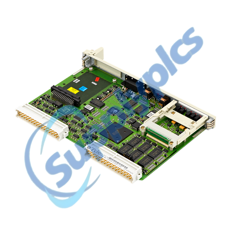
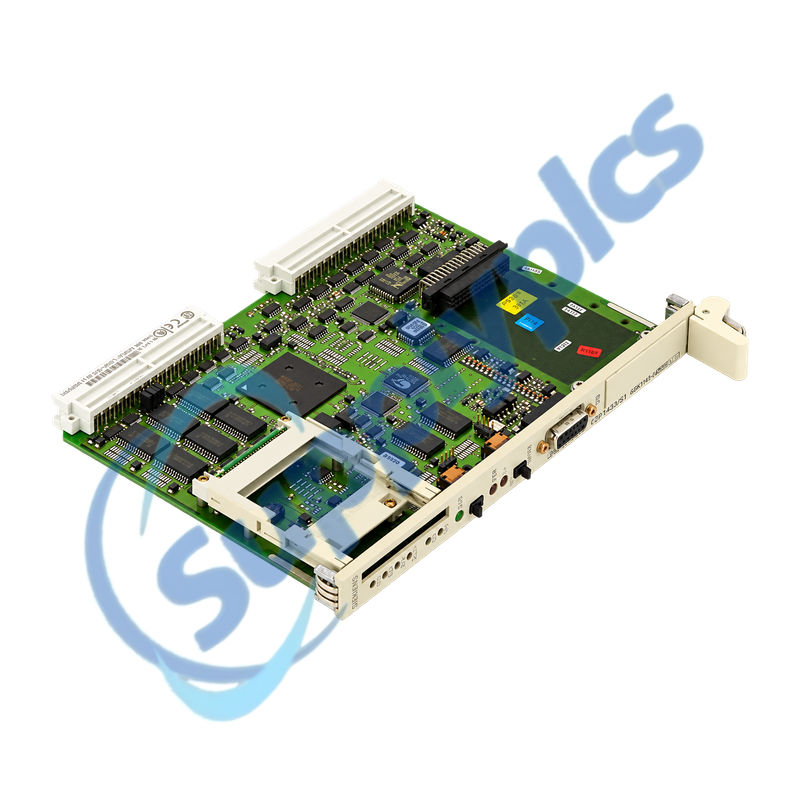
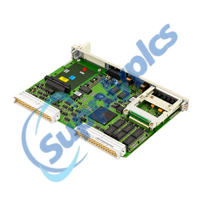
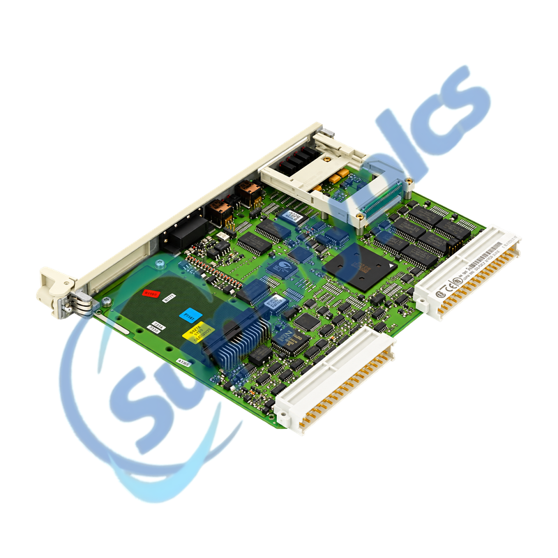
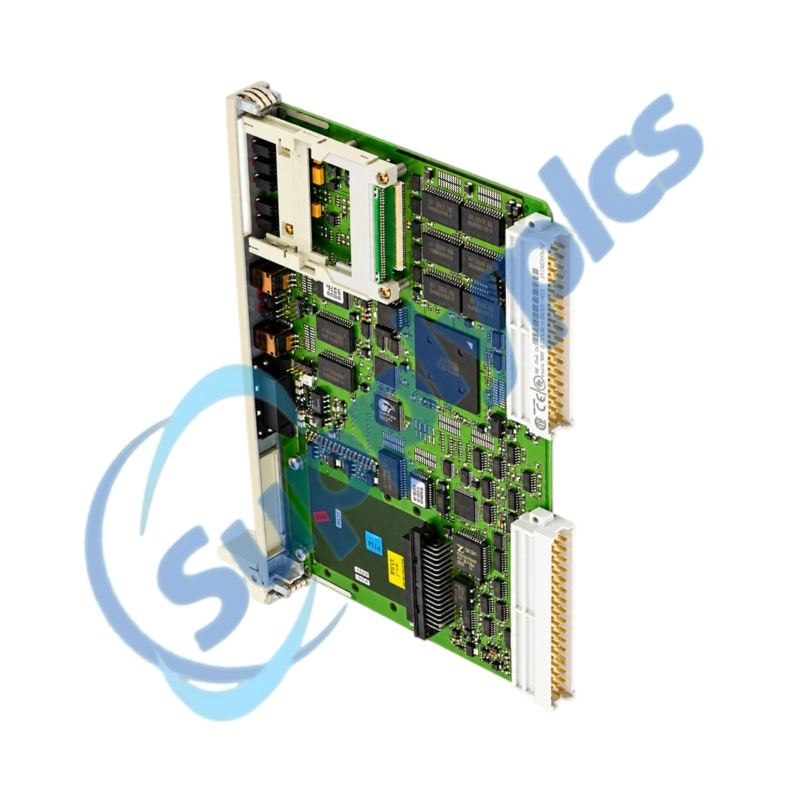
High-capacity SIMATIC S5 CPU for S5-155U single-processor and multiprocessor systems
The CPU 948-2 executes cyclic, time-controlled and interrupt-driven STEP 5 programs in legacy S5-155U automation systems. Its internal program memory, PG interface and optional serial-interface submodules make the installed memory card, rack assignment and archived STEP 5 project central to a reliable replacement.
Controlled CPU exchange: Match the full order number, rack and slot, CPU operating mode, memory-card type and contents, interface submodule, I/O addressing and STEP 5 program before the original controller is removed.
CPU Recovery
In established S5-155U installations, 6ES5948-3UA23 provides the CPU 948-2 processing platform with 1664 KB of internal RAM and support for cyclic, timed and interrupt-controlled execution. The module can be used in single-processor or coordinated multiprocessor configurations, so the rack role is part of the product identity.
A successful service replacement depends on preserving more than the user program. The memory card, DB and DX organization, process-image configuration, PG interface settings and any fitted SI1 or SI2 interface module affect how the controller starts and communicates after installation.
Preserve the STEP 5 software, memory media and rack context before disturbing a working CPU.
STEP 5 archive
Save the complete project, symbol information, DB and DX contents and the online comparison result while the original station is still accessible.
Memory-card identity
Record the card type, capacity, write-protection state and relationship between the card image and the program loaded in internal RAM.
Rack and processor role
Photograph the slot and neighboring modules and document whether the station uses one CPU or a coordinated multiprocessor arrangement.
LED Diagnostics
The CPU display and diagnostic stack help separate program, peripheral and interface faults after service work.
STOP and SYS FAULT
Read the diagnostic stack before an overall reset; a program or hardware fault can otherwise be replaced by a loss of evidence.
QVZ and ADF events
Compare missing-peripheral and addressing faults with the recorded I/O configuration, rack layout and process-image limits.
SI1 and SI2 channels
When serial communication is affected, match the fitted interface module, transmission standard, parameters and connector assignment.
How should a maintenance engineer confirm that 6ES5948-3UA23 belongs in the existing S5-155U rack?
Match the full CPU label, rack and slot and determine whether the station is single-processor or multiprocessor. Compare the installed memory card, optional SI1 or SI2 interface and the STEP 5 hardware and I/O configuration before approving the spare.
Q2
What should be backed up before a plant replaces 6ES5948-3UA23 during a shutdown?
Save the complete STEP 5 project, online program and DB or DX contents, memory-card image and diagnostic stack. Also record the rack layout, processor role, interface parameters and normal LED state so commissioning can reproduce the original operating context.
Q3
Why can 6ES5948-3UA23 remain in STOP after the program has been reloaded?
The CPU can stay in STOP when the memory-card content, processor assignment, I/O addressing or restart conditions do not match the project. Read the diagnostic stack and STOP or SYS FAULT indications before attempting an overall reset.
Q4
How can a technician isolate recurring QVZ faults after installing 6ES5948-3UA23?
QVZ points to a peripheral access problem rather than proving a CPU defect. Use the reported address to trace the affected rack, interface module and I/O card, then compare the physical configuration with the STEP 5 address map and process image.
Q5
What should be reviewed when the serial link on 6ES5948-3UA23 does not recover?
Identify whether SI1 or SI2 is used and match the fitted interface submodule to V.24, TTY or RS422/485 operation. Restore the original baud rate, frame parameters, cable pinout and partner settings before changing CPU hardware.
Q6
When is an overall reset appropriate for 6ES5948-3UA23 after maintenance?
Use it only after the current program, data blocks and diagnostics have been secured and the cause of STOP is understood. An overall reset clears controller memory, so it should be followed by loading the verified project and checking I/O and communication in a controlled start-up.


 EN