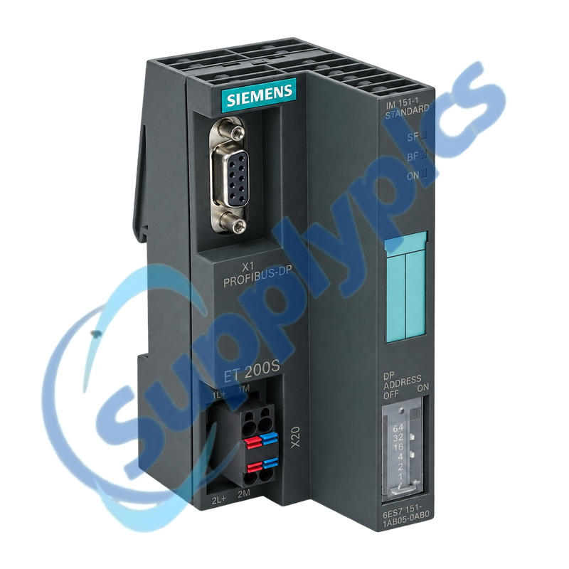
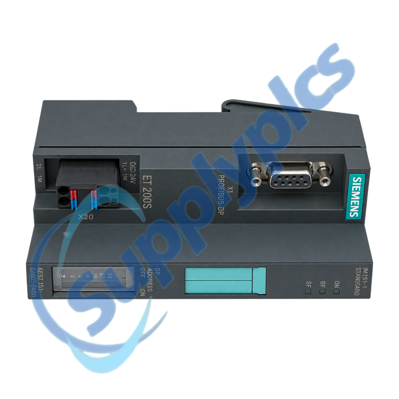
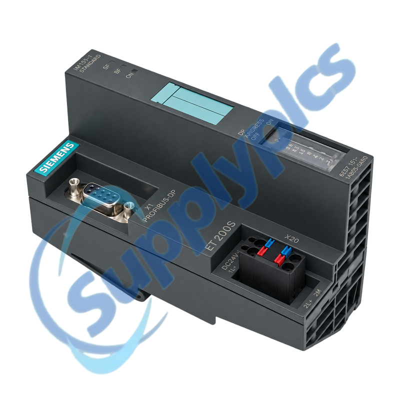
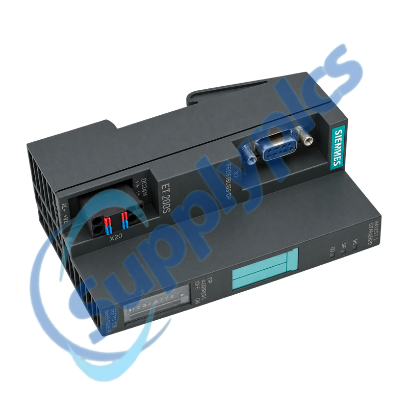
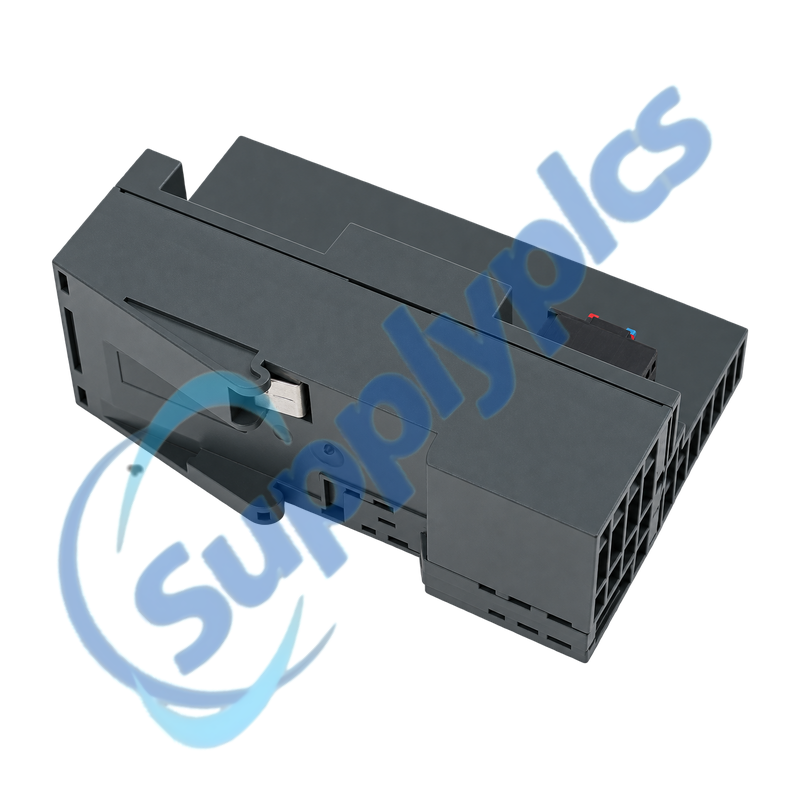
ET 200S PROFIBUS interface module with integrated fiber-optic bus connection
The IM151-1 FO connects an ET 200S station to PROFIBUS through its integrated optical interface and supports up to 63 ET 200S power, electronic or motor-starter modules. Replacement requires the exact optical topology, PROFIBUS address, station configuration and termination module.
Station compatibility check: Confirm the full 6ES7151-1AB05-0AB0 label, ET 200S terminal-module arrangement, optical connectors and partner, PROFIBUS rate and address, expected module list, total input and output data and the supplied termination module before removal.
FO Integration
6ES7151-1AB05-0AB0 is the SIMATIC ET 200S IM151-1 FO interface module for a fiber-optic PROFIBUS station. It manages the station backplane and exchanges up to 244 bytes of input and 244 bytes of output data with the DP master.
The module is a discontinued spare, so exact station evidence matters. Export the hardware configuration, photograph the terminal sequence and optical routing and record the PROFIBUS address, baud rate, LEDs and diagnostic buffer before the station is de-energized.
The optical path and the configured ET 200S station must agree end to end.
Fiber map
Record connector direction, partner station, cable route, fiber condition and every intermediate coupler.
DP identity
Preserve the PROFIBUS address, baud rate, master project and the station input and output address areas.
Terminal sequence
Photograph each ET 200S module and terminal position and retain the termination module at the station end.
Module Setup
Use the LED pattern and master diagnostics to identify the first mismatch.
Configuration match
Compare the physical module sequence with the downloaded hardware configuration before enabling outputs.
Optical diagnosis
Inspect and clean the optical connectors and compare both-end status before replacing the interface.
Station recovery
Commission with the machine safe, verify each IO group and retain the final diagnostic record.
Specifications
Product type designation
SIMATIC ET 200S IM151-1 FO
Order number
6ES7151-1AB05-0AB0
Fieldbus
PROFIBUS DP over integrated fiber optics
Maximum transmission rate
12 Mbit/s
Input data capacity
Up to 244 bytes
Output data capacity
Up to 244 bytes
Station expansion
Up to 63 ET 200S modules
Supported station modules
Power, electronic and motor-starter modules
Station termination
Termination module required and originally included
How can I verify that 6ES7151-1AB05-0AB0 matches the installed ET 200S station?
Match the complete IM151-1 FO order number, optical connector arrangement, terminal-module system and termination module. Compare the PROFIBUS address and rate, module sequence and configured input and output lengths with the STEP 7 or DP-master project.
Q2
What should be documented before replacing 6ES7151-1AB05-0AB0?
Export the hardware configuration and diagnostics, photograph the complete ET 200S module order and label both optical paths. Record the PROFIBUS address, transmission rate, normal LEDs, termination module and the physical position of every power and electronic module.
Q3
Why can 6ES7151-1AB05-0AB0 show a bus fault after a like-for-like exchange?
Check the restored PROFIBUS address and baud rate, optical transmit and receive routing and the master configuration. Compare the actual ET 200S module sequence with the project and verify that the station termination module is installed correctly.
Q4
How can I isolate an optical-path fault from a station-configuration fault on 6ES7151-1AB05-0AB0?
Compare the interface and master diagnostics with the partner optical indication. Clean and reseat the approved fiber connectors and verify transmit-to-receive routing; if the optical link is healthy, use the diagnostic buffer to identify the first missing or mismatched ET 200S module.
Q5
What should I check when 6ES7151-1AB05-0AB0 reports a missing module after maintenance?
Compare the physical order with the saved hardware project, including power modules and motor starters. Inspect terminal-module seating and the backplane connection at the reported position, then replace or reseat only with the station safely de-energized.
Q6
Can another IM151-1 variant replace 6ES7151-1AB05-0AB0 without engineering changes?
Do not assume interchangeability from the IM151-1 name. Copper and fiber variants, station limits, diagnostics and firmware support differ; verify the full order number and approved substitute, update the hardware configuration if required and recommission every affected IO channel.


 EN