Home > Products > SIEMENS > SIMATIC S7 Series
|
CHANNELS
8 voltage inputs, single-ended
|
RANGES
0 to 10 V; -10 to +10 V
|
|
RESOLUTION
Up to 16 bit
|
BASEUNIT
Type A0 or A1; color code CC02
|
|
LEAD TIME
In stock
|
WARRANTY
1 year
|

CHANNELS
8 voltage inputs, single-ended
|
RANGES
0 to 10 V; -10 to +10 V
|
RESOLUTION
Up to 16 bit
|
BASEUNIT
Type A0 or A1; color code CC02
|
|
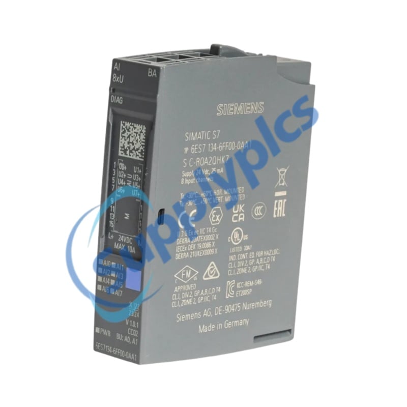
Complete model
|
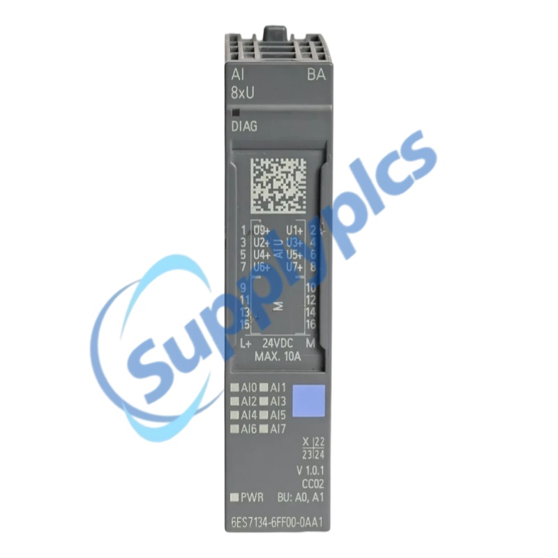
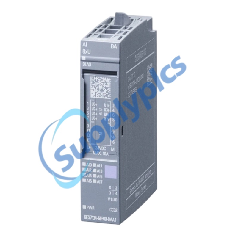
6ES7134-6FF00-0AA1
|
|
Product family
|
SIMATIC ET 200SP analog input modules
|
|
Product type
|
AI 8xU Basic
|
|
Inputs
|
8 single-ended analog voltage inputs
|
|
Input ranges
|
0 to +10 V; -10 to +10 V
|
|
Resolution
|
15 bit for 0 to 10 V; 16 bit including sign for -10 to +10 V
|
|
Input resistance
|
100 kOhm
|
|
Cycle time
|
Minimum 1 ms per channel
|
|
Cable length
|
Shielded, maximum 200 m
|
|
Basic error at 25 deg C
|
Plus/minus 0.3% of input range
|
|
Operational error
|
Plus/minus 0.5% over total temperature range
|
|
Diagnostics
|
Supply monitoring, group error and overflow/underflow
|
|
BaseUnit
|
Type A0 or A1; 1-wire or 2-wire connection
|
|
Supply voltage
|
24 V DC; 19.2 to 28.8 V
|
|
Current consumption
|
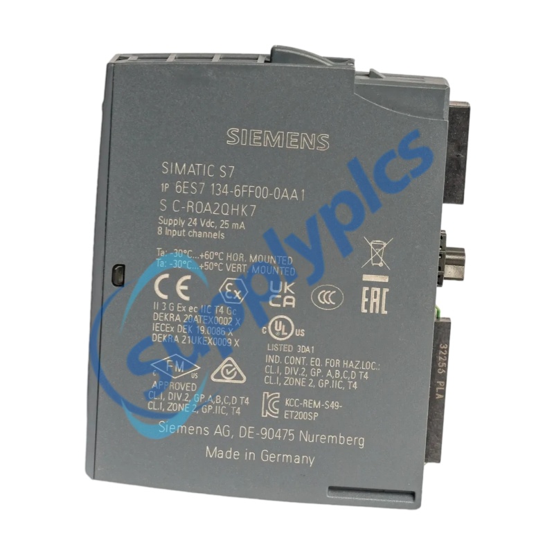
25 mA
|
|
Power loss
|
Typical 0.7 W
|
|
Operating temperature
|
Horizontal: -30 to +60 deg C; vertical: -30 to +50 deg C
|
|
Dimensions
|
15 x 73 x 58 mm (W x H x D)
|
|
Weight
|
Approx. 31 g
|
|
Voltage acquisition
Acquire eight single-ended voltage signals from industrial sensors and transmitters.
|
Compact distributed I/O
The 15 mm ET 200SP format increases channel density in remote I/O stations.
|
|
Configurable filtering
Selectable integration time and four smoothing levels support signal conditioning.
|
Module diagnostics
PWR, DIAG and channel-status LEDs assist commissioning and service.
|
|
Input architecture
Eight single-ended voltage inputs with no channel-to-channel isolation.
|
Range support
0 to +10 V at 15 bit and -10 to +10 V at 16 bit including sign.
|
|
BaseUnit interface
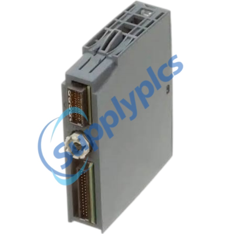
Fits BU type A0 or A1 with 1-wire or 2-wire connection variants.
|
Isolation
Channels are isolated from the backplane bus and tested at 707 V DC.
|
|
1. BaseUnit
|
Install on a compatible A0 or A1 BaseUnit and observe type B mechanical coding.
|
|
2. Wiring
|
Use the documented 1-wire or 2-wire voltage connection and shielded cable where required.
|
|
3. Range setup
|
Assign 0 to 10 V or -10 to +10 V for each application channel.
|
|
4. Engineering
|
Configure the exact module in the supported STEP 7, PROFIBUS GSD or PROFINET GSDML environment.
|
|
5. Commissioning
|
Verify PWR, DIAG and channel LEDs, then validate scaling and diagnostic behavior.
|
|
Signal type
Use this model for voltage inputs only; it does not support four-wire current transmitters.
|
Channel count
Confirm eight single-ended channels meet the application.
|
|
Accuracy
Check the plus/minus 0.3% basic and plus/minus 0.5% operational error limits.
|
Mechanical fit
Confirm A0/A1 BaseUnit, CC02 color code and 15 x 73 x 58 mm space.
|
|
Recommend model
|
||
|
T1E/A 1SDA059582R1
|
XD26 88974163
|
MNB-V2-2
|
|
X12091814-1ABS
|
HSN-6A
|
1771-P6S/B
|
|
MIL-RC3412-V2
|
PDL4335
|
2CDG 110 027 R0011
|
|
MTN649315 Reg-K/4X230
|
GSS SDC 17/24
|
MA1472C
|
|
XC-1000A-7
|
ABB AO523 1SAP450200R0001
|
SB500
|
|
ET-788
|
P-300 05273-101S
|
CDH4U5-B
|
|
FMZ5000 903466
|
RS900-HI-D-C2-C2-00
|
B&R 7CP470.60-2
|
|
ABB TU810V1 3BSE013230R1
|
VI-13800
|
MC55A0 MC55A0-P40SWQQA9WR
|
|
CMAS_AT_000002E
|
CAB 5004
|
HBW4GR1V
|
|
FS-QS-1210-0285
|
P2WL-P
|
UMM-250
|
|
DR-4524
|
SC8551A005MS.24
|
RO4 400018
|
|
CH-HRIO8-D9
|
GE RE2M 101873
|
QAA25
|
|
M88251-001
|
CI-205-1
|
P4R-HF 722-746
|
|
PAC4200 7KM4212-0BA00-3AA0
|
LV434010 IFE-E3.16.36
|
SNH-G01-AR-MR-D2-11
|
|
IRC5704-MW
|
TMPU-750 17-505750-001
|
ABB CEM05100 2CMA137121R1000
|
|
RP128KCLPILA
|
TB541-ETH 1SAP114100R0270
|
NetAXS-123
|
|
E2-16DO24-D
|
IC-M304
|
CR1-RJ
|
|
PN:2320186
|
KFD2-GS-1.2W PN:38311
|
ABB AI523 / 1SAP250300B0001
|
|
PG4945
|
RS232-FO 7XV5652-0BA00/BB
|
2160/EUI
|
|
SB2-ZAM
|
PCO1DH0CM0
|
AWK-3121-US-T
|
 EN