Home > Products > SIEMENS > SIMATIC S7 Series
|
TERMINALS
16 process + 10 AUX |
RATED VOLTAGE
24 V DC |
|
CURRENT CAPACITY
P1/P2 and AUX: 10 A |
SIZE
15 × 141 × 35 mm |
|
LEAD TIME
In stock |
WARRANTY
1 year |

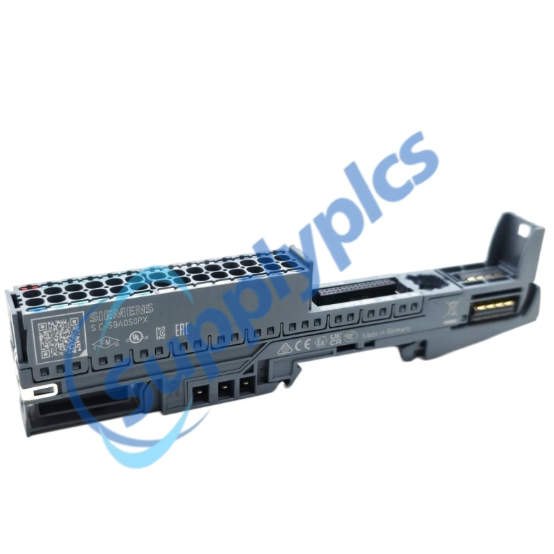
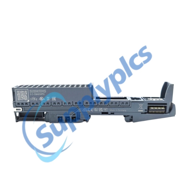
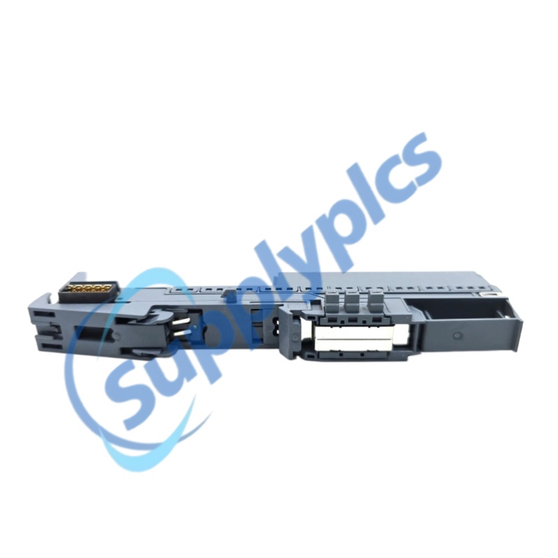
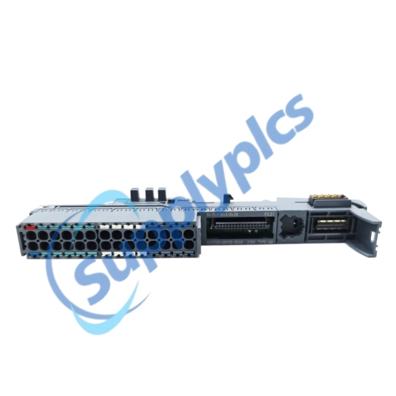
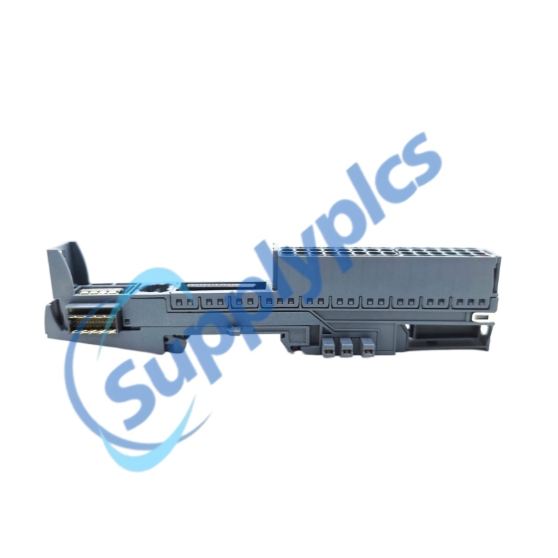
The SIEMENS 6ES7193-6BP20-0BA0 is a dark-colored SIMATIC ET 200SP BaseUnit BU15-P16+A10+2B of type A0. It uses push-in terminals, provides 16 process terminals and 10 AUX terminals, and continues the potential group from the BaseUnit installed on its left.
Compact station base The 15 mm wide BaseUnit provides the mechanical and electrical base for one compatible ET 200SP I/O module. |
Integrated auxiliary distribution Ten AUX terminals are bridged as a group for auxiliary potential distribution within the station design. |
Defined current paths The official limits are 10 A for P1/P2, 10 A for the AUX bus, and 2 A for each process terminal. |
|
Complete model
|
6ES7193-6BP20-0BA0
|
|
Product family
|
SIMATIC ET 200SP BaseUnits
|
|
Product type
|
BU15-P16+A10+2B, BU type A0
|
|
Terminal technology
|
Push-in terminals
|
|
Rated supply voltage
|
24 V DC
|
|
P1 and P2 bus current capacity
|
Maximum 10 A
|
|
AUX bus current capacity
|
Maximum 10 A
|
|
Process terminal current capacity
|
Maximum 2 A
|
|
Potential group behavior
|
Continues the potential group from the left; does not create a new group
|
|
Process terminals
|
16
|
|
AUX terminals
|
10
|
|
P1/P2 terminals
|
2
|
|
Conductor cross-section
|
0.14 to 2.5 mm²; AWG 26 to AWG 14
|
|
Isolation test voltage
|
707 V DC type test
|
|
Dimensions (W × H × D)
|
15 × 141 × 35 mm
|
|
Weight
|
Approx. 50 g
|
|
Operating temperature, horizontal
|
-30 °C to +60 °C
|
|
Operating temperature, vertical
|
-30 °C to +50 °C
|
|
Installation altitude
|
Up to 5,000 m; restrictions apply above 2,000 m
|
|
Distributed I/O stations
Use the BaseUnit as the wiring and mounting base for one compatible type A0 ET 200SP I/O module. |
|
Auxiliary potential distribution
The ten AUX terminals support organized distribution of an auxiliary potential through the assigned terminal group. |
|
Compact control cabinets
Its 15 mm width supports dense ET 200SP station layouts while keeping field wiring accessible. |
|
Maintained field wiring
The separable module-and-BaseUnit concept allows the electronics module to be handled without rebuilding the complete terminal structure. |
|
Process terminals
|
16 push-in terminals assigned to the I/O module
|
|
AUX terminals
|
10 terminals, internally bridged as an AUX group
|
|
P1/P2 connection terminals
|
2
|
|
Wire range
|
0.14 to 2.5 mm²; AWG 26 to AWG 14
|
|
Shield connection
|
Optional system-integrated shield connection
|
|
Module slot
|
One slot for a compatible BU type A0 I/O module
|
|
No new group
This dark-colored type A0 BaseUnit does not open a new potential group. |
|
Continuation from the left
P1, P2, and the AUX potential are continued from the compatible BaseUnit installed on the left. |
|
Current-limit check
Engineering must keep P1/P2 and AUX bus loading within 10 A and each process terminal within 2 A. |
|
Isolation verification
The official type test value is 707 V DC between the specified electrical sections. |
|
Confirm module compatibility
Verify that the planned ET 200SP I/O module requires BU type A0 and the BU15-P16+A10+2B terminal arrangement. |
|
Mount on the station rail
Install the BaseUnit in the correct station order and ensure the potential bars engage with the neighboring BaseUnit. |
|
Prepare conductors
Strip and insert conductors within the published 0.14 to 2.5 mm² range using the push-in terminal procedure. |
|
Check potential continuity
Confirm the left-fed potential group, AUX bridge assignment, polarity, and protective device before applying 24 V DC. |
|
Inspect the finished station
Verify terminal seating, label positions, module latching, and current allocation before startup. |
|
MB3170/KC
|
A172-A 1550/1310
|
E1210-T
|
|
543-607 IDS-10100
|
TPMC-8L-FPW-T-NB
|
RXV-35-4K / 4K
|
|
DDM-163 05-008-163 DKL-013
|
HDL-MAC01.231
|
CH-LMD1
|
|
SB-3SBXS-WL
|
Y7512-5335
|
2866679 QUINT-PS/1AC/48DC/ 5
|
|
AMX526
|
SEC-TEA-230-5045
|
1785ME32 Q01PLC5
|
|
ABB 3BSE013210R1 DI830
|
DPTM500
|
OTM1000
|
|
CMD5B2000
|
2CDG110081R0011
|
NBD-768A ASC CFL-451A
|
|
PREMTB001
|
AKM115SF132
|
3HAB8101-8/14A - DSQC346G
|
|
EPX420D
|
NP08ZL
|
35UB R890005B2
|
|
ABB 2CDG 110 153 R0011
|
ABB TA25DU 1SAZ211201R1025
|
MTDUVR120V
|
|
AS-BDE0-216
|
KFD2-VR4-EX1.26
|
ABB 110A-150A TA200DU-150 1SAZ421201R1004
|
|
554 15D137510
|
ABB GSNE000700R5312 - 23BA20
|
CCT15369
|
|
CPG1000-BEL-AJZZZ3-Z
|
J9008A
|
EM 100 G3
|
|
XM669K-5P1C1 MGFDDIC501
|
ABB 6220-0-0117 SU-F-1.0.1
|
S7-400HP 20A 6EP8090-0CA00
|
|
ECP-300
|
SB401-10-S1
|
DDRC810DT-GL-DC
|
|
HRCPDG42R
|
MLR3000
|
KMD-1161W
|
|
IJ-PR-95-265
|
FM3200B-GPS-HW-US
|
APL21-06E PD-3501G/AC
|
|
EC-600
|
VPM35 3BA73012ABAB03
|
PM500 50980
|
|
BZMB1-A40-BT
|
DDI161 05-006-161 DKL011
|
AJ65BTB2-16D
|
|
7NG4021-6AA33-0NN0
|
ABB DC523 A0 1SAP 440500R0001
|
3AL78836ADAB 03
|
 EN