Product Name: Exciter Power Distribution Module
Brand Name: GE
Model Number:IS200EPDMG1BAA
Country of Origin:USA
Warranty: 12 Months
Whatsapp:+86 18159889985
Email:[email protected]

Brand Name: |
General Electric |
Model Number: |
IS200EPDMG1BAA |
Country of Origin: |
USA |
Packaging Details: |
Original new Factory Sealed |
Delivery Time: |
Delivery time in stock |
Payment Terms: |
T/T |
|
Sales Manager: |
Stella |
|
Send an email: |
|
|
Contact in Whatsapp: |
|
Part Number |
IS200EPDMG1BAA |
|
Functional Acronym |
EPDM (Exciter Power Distribution Module) |
|
Manufacturer |
General Electric (GE) – GE Vernova / Baker Hughes |
|
Series |
EX2100 / EX2100e Excitation Control System, Mark VI / Mark VIe Speedtronic |
|
Product Type |
Exciter Power Distribution Module (Low-Voltage Control Power Hub) |
|
PCB Technology |
Surface mount |
|
Country of Origin |
United States (USA) |
|
Power Inputs |
|
|
Primary Input Voltage |
125 V DC (station battery) |
|
Backup Input Voltage |
Up to two separate 120 V AC 50/60 Hz inputs (external DACA converters rectify to 125 V DC) |
|
DC Input after Rectification |
Nominally +62.5 V and –62.5 V to ground (center-grounded 125 V) |
|
Power Outputs & Distribution |
|
|
DC Outputs for Exciter Boards |
+5 V, +15 V, +24 V, ±24 V, +70 V isolated, +28 V (via EPSM / EPBP backplane) |
|
Maximum Load Current |
Up to 100 A (system-level) |
|
Output Connections |
Up to 6–8 regulated outputs from EPBP backplane; 24-point terminal block (TB1) for filtered power distribution |
|
Pluggable Connectors (JDACA1, JDACA2, etc.) |
Approximately 10 plug connectors |
|
Component Protection & Control |
|
|
Fuses |
14 replaceable fuses (3.15 A for EGPA/EXTB, 8.0 A for EPSM) – per-output overcurrent protection |
|
Switches |
7 toggle switches (SW1–SW6 populated, SW7 spare) rated 125 V DC / 6 A; per-output on/off isolation |
|
LEDs |
8 green LED indicators (DS1–DS7 populated, DS8 spare) – visual power-available status |
|
Grounding |
4 chassis / safety-grounded mounting holes (separate networks: CHASGND1, CHASGND, SFTYGND) |
|
Physical & Environmental |
|
|
Dimensions (W × H × D) |
33.02 cm × 17.8 cm × approx. 10 cm |
|
Weight |
0.36 kg – 1.45 kg (source-dependent) |
|
Mounting Type |
Side-mounted on EPBP backplane in EX2100 cabinet |
|
Protection Rating |
IP20 (enclosure required) |
|
Conformal Coating |
Yes – industrial-grade protective coating for harsh environments |
|
Operating Temperature |
–20 °C to +60 °C ( –40 °C to +70 °C for some variants) |
|
Storage Temperature |
–40 °C to +85 °C |
|
Humidity |
5% – 95% RH, non-condensing |
|
Altitude |
Up to 2000 m |
|
Certifications & Compliance |
|
|
Connector Voltage Rating |
600 V AC / DC |
|
Terminal Block Rating |
300 V, 10 A per pin |
|
Compliance |
UL 508, CSA, CE, RoHS, ATEX Zone 2 (with appropriate enclosure) |
|
Associated Manual |
GEI-100488 (EX2100 Excitation Control Product Description) |
|
Availability |
In Stock |
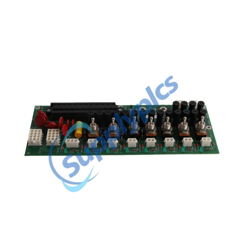
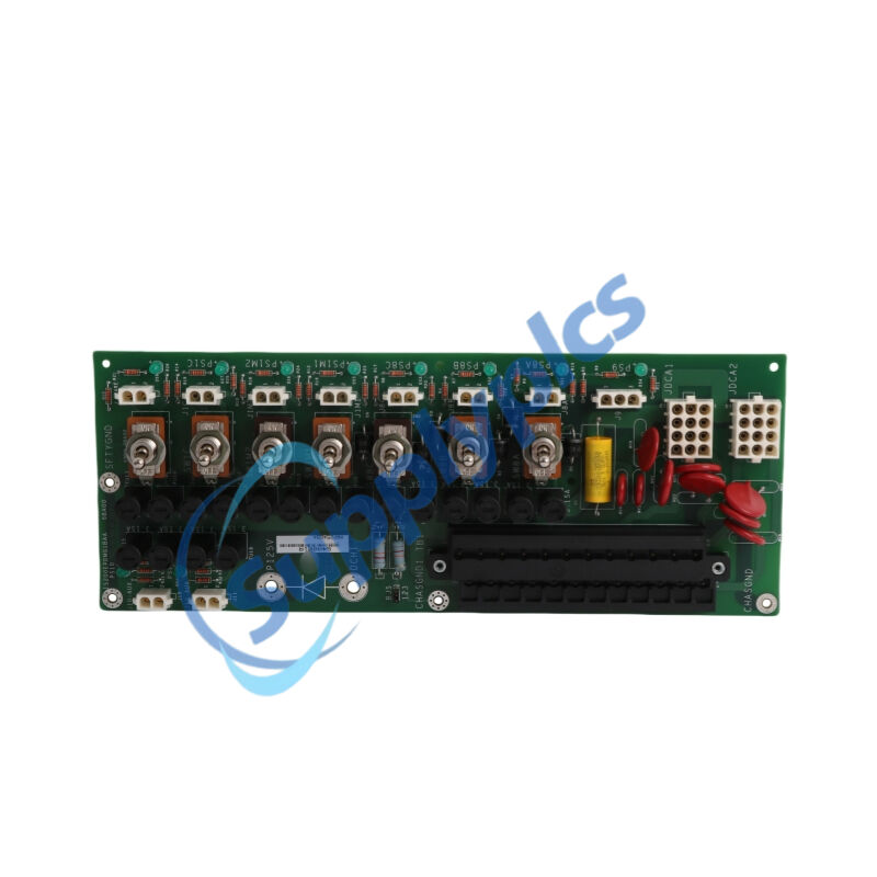
The IS200EPDMG1BAA (EPDM – Exciter Power Distribution Module) is a primary low‑voltage control power hub engineered by General Electric for the EX2100 excitation control system, itself integrated into the Mark VI / Mark VIe Speedtronic turbine platform. The IS200EPDMG1BAA receives filtered 125 V DC primary power from the station battery and optionally one or two redundant 120 V AC backup inputs, which are externally rectified to 125 V DC by DACA converters. Power is then distributed through the EPBP backplane to exciter control boards, I/O cards, gate pulse amplifiers (EGPA), terminal boards (EXTB), and EPSM power supply modules. With 14 fuses, 7 toggle switches, and 8 LED status indicators, the IS200EPDMG1BAA provides modular, protected, and continuously monitored power for safe turbine start‑up and steady‑state operation.
EX2100 / EX2100e Excitation Control Systems – prime AC / DC primary power source distribution to exciter boards
GE Mark VI / Mark VIe Speedtronic gas and steam turbine generator sets – delivers low‑voltage control power to the exciter subsystem
Power plants (combined‑cycle, coal‑fired, hydro, nuclear conventional island) – central power hub in the exciter cabinet
Industrial power generation and cogeneration – provides redundant AC + DC power distribution for continuous availability
Oil & gas turbine‑driven compressor stations – powers excitation controls in hazardous or remote locations
EX2100 exciter retrofit / upgrade projects – direct replacement for legacy EPDM modules
Marine propulsion and offshore platform turbine control – supports isolated grounding and redundant power feeds
High‑availability excitation systems – where dual AC backup and DC station battery ensure uninterrupted field current
Primary 125 V DC + dual 120 V AC redundant power inputs – EPDM receives 125 V DC from the station battery as the primary source and accepts up to two separate 120 V AC 50/60 Hz inputs (connected via JDACA1 and JDACA2) for redundant backup.
External AC‑to‑DC conversion by DACA modules – Backup AC inputs are rectified to 125 V DC by external AC to DC Converters (DACA#1 and DACA#2), which are returned to the EPDM via JDACA connectors before distribution.
Center‑grounded ±62.5 V DC output rails – The resulting 125 V DC power is configured as nominally +62.5 V and –62.5 V to ground, ensuring balanced reference and stable supply for exciter analog control and I/O circuits.
14 replaceable fuses with per‑output overcurrent protection – Provides fault isolation for each individual power output: 3.15 A fuses for EGPA boards and EXTB, 8.0 A fuses for EPSM modules (fuses FU1–FU6 and FU7–FU12 populated).
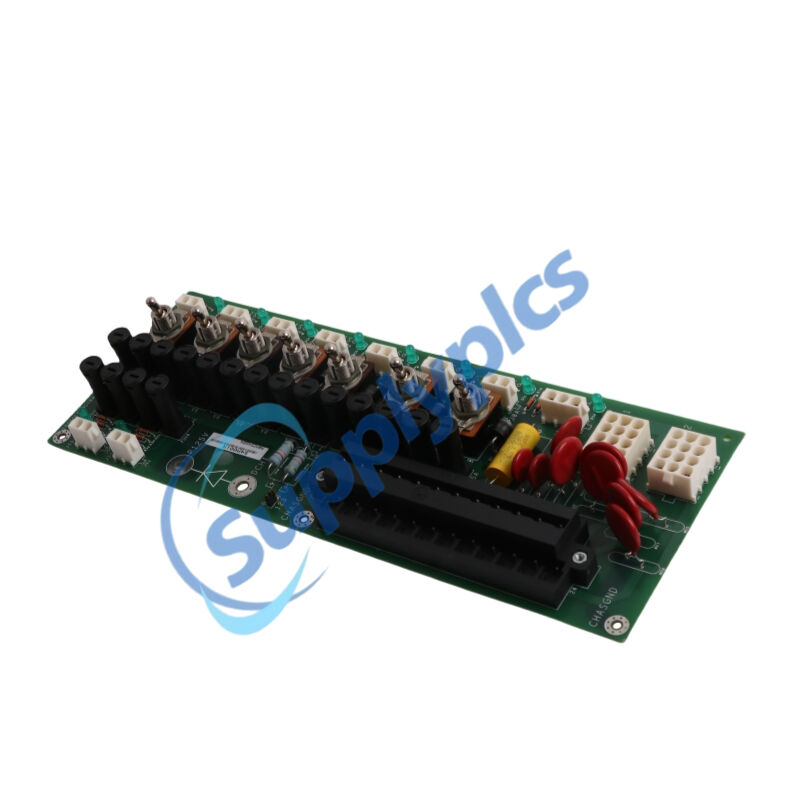
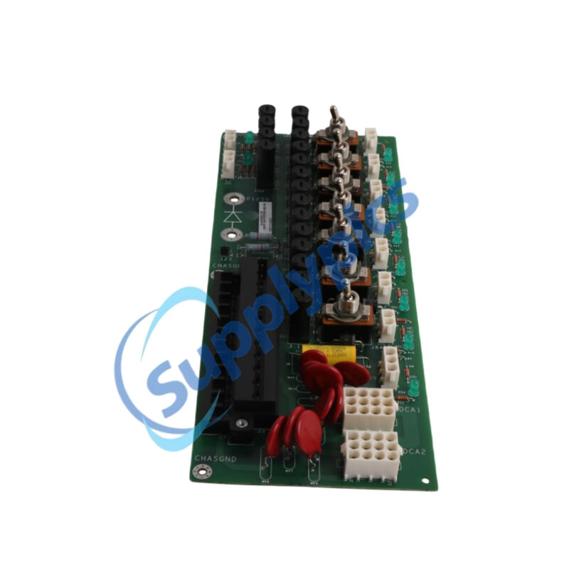
7 toggle switches for per‑circuit isolation – SW1–SW6 control power to three EGPA boards and three EPSM modules; each switch rated 125 V DC / 6 A, enabling live maintenance and troubleshooting of individual branches.
8 green LED status indicators for power availability – DS1–DS3 illuminate when EGPA boards receive power, DS4 for EXTB, DS5 for M1 EPSM, DS6 for M2 EPSM, and DS7 for C EPSM – at‑a‑glance confirmation of all voltage rails.
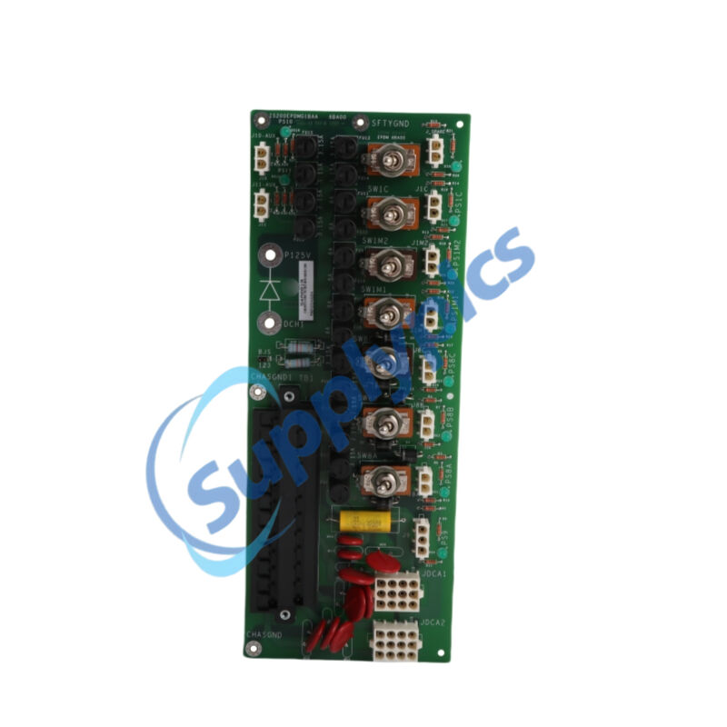
24‑point terminal block (TB1) for filtered power input and distribution – A 24‑pin terminal block rated 300 V / 10 A receives and passes filtered AC and DC inputs, providing flexible field connection options.
Over‑voltage, over‑current, reverse polarity and thermal protection – Built‑in varistors (MOVs), fuses, and soft‑start circuit on the input line limit inrush current and protect downstream electronics from power surges and accidental reverse connections.
Isolated grounding architecture (three separate ground networks) – CHASGND1 (input filter return), CHASGND (main chassis ground), and SFTYGND (switch body safety ground) all tied separately to prevent ground loops and improve system immunity.
Hot‑swap capable with upstream power disconnected – Supports in‑cabinet replacement while exciter remains powered down, minimising downtime for module swaps.
RS‑485 serial communication interface for status reporting – Provides diagnostic channel to the exciter controller for remote monitoring of power availability, fuse status, and thermal alarms without local inspection.
Conformal coating for harsh industrial environments – PCB is conformally coated to resist moisture, dust, chemical contamination, and vibration, ensuring reliable operation in turbine enclosures and outdoor substations.
Side‑mount design onto EPBP backplane – Directly bolts to the side of the Exciter Power Backplane (EPBP) and connects via multiple plug connectors, eliminating external wiring between power supply and distribution stages.
Easy field replacement without soldering – All connectors, switches and fuses are mechanically or pluggably attached; no soldering required for removal or reinstallation.
Global hazard location certifications (optional) – Select versions are certified for ATEX Zone 2, IECEx, and UL Class I Division 2 hazardous locations when used with appropriate enclosures and wiring methods.
Fully compatible with EX2100 and Mark VI spare parts ecosystem – Interchangeable with older EPDM revisions, supporting legacy system upgrades without rewiring or software changes.
Receives and filters incoming 125 V DC (primary) and up to two 120 V AC (backup) power inputs via a 24‑point terminal block (TB1), then routes the filtered power to the JDACA connectors for external conversion.
Converts externally rectified 125 V DC from DACA modules into centre‑grounded ±62.5 V rails on the P125V and R125V lines, providing balanced and isolated DC power for exciter control and I/O circuits.
Distributes 125 V DC power through EPBP backplane to up to 6–8 exciter boards – specifically three Exciter Gate Pulse Amplifier boards (EGPA), one Exciter Terminal Board (EXTB), and three Exciter Power Supply Modules (EPSM) for M1, M2, and C controllers.
Protects each output branch with dedicated fuses (14 total) – 3.15 A fuses safeguard EGPA and EXTB circuits; 8.0 A fuses protect EPSM branches; a blown fuse opens its output and darkens its corresponding LED, indicating the faulted branch.
Allows manual isolation of each power output via 6 toggle switches (SW1–SW6) – Switches rated 125 V DC / 6 A enable individual de‑energising of EGPA and EPSM circuits for live maintenance, troubleshooting, or fault isolation without disturbing other exciter functions.
Provides real‑time visual power‑available status through 7 green LED indicators – Illuminates when each output is energised and healthy; dark LED immediately signals absence of power on that branch, streamlining on‑site diagnostics.
Grounds the module chassis and switches via four dedicated grounding holes – Chassis ground (E2) and safety ground (E3, E4) provide separate return paths, while CHASGND1 grounds the input power filters, minimising electrical noise on control circuits.
Safely manages inrush current at power‑up – Built‑in soft‑start circuit and input filter limit startup current, protecting external power supplies and preventing voltage drop on the station battery or AC backup lines.
Reports diagnostic status (blown fuse, open switch, temperature exceedance) through EPBP backplane – Signals are monitored by the exciter controller; out‑of‑range conditions generate alarms in the HMI and can trigger fail‑safe transfer logic.
Electrically isolates input and output circuits via galvanic barriers – Blocks conducted EMI and surge transients from propagating from the field wiring to the exciter backplane, protecting sensitive processor and I/O boards.
Dissipates fault energy through 130 V AC metal oxide varistors (MOVs) – Integrated MOVs on each output absorb voltage spikes from switching inductive loads (field breakers, contactor coils), suppressing transients that could damage downstream electronics.
Passes exciter controller‘s diagnostic queries via RS‑485 serial link – Allows remote verification of fuse integrity, switch position, and power supply health, integrating EPDM status into plant‑wide monitoring systems without on‑site inspection.
Enables field‑upgradable configuration with ToolboxST software – The associated exciter CPU can read EPDM‘s electronic ID and board revision; no manual jumpers are required, and all power distribution parameters are set in system firmware.
Q1: What is the primary role of the IS200EPDMG1BAA in an EX2100 excitation system?
A1: The IS200EPDMG1BAA (EPDM) acts as the central low‑voltage power distribution hub. It receives filtered 125 V DC from the station battery and optional 120 V AC backup inputs, then distributes protected, regulated power to EGPA gate amplifier boards, EXTB terminal board, and EPSM power supply modules via the EPBP backplane.
Q2: What power inputs does the IS200EPDMG1BAA accept, and how are AC inputs handled?
A2: It accepts one primary 125 V DC input (station battery) and up to two separate 120 V AC inputs (50/60 Hz) for redundant backup. Each AC input is routed to an external AC‑to‑DC Converter (DACA module) that rectifies it to 125 V DC before being returned to the EPDM for distribution.
Q3: How many fuses, switches, and LED indicators does the IS200EPDMG1BAA have?
A3: The IS200EPDMG1BAA features 14 replaceable fuses (3.15 A and 8.0 A ratings), 6 toggle switches for per‑output isolation (plus one spare switch position), and 7 green LED status indicators – one for each powered EGPA board, EXTB, and EPSM module.
Q4: What exciter boards receive power from the IS200EPDMG1BAA ?
A4: Up to three Exciter Gate Pulse Amplifier (EGPA) boards, one Exciter Terminal Board (EXTB), and three Exciter Power Supply Modules (EPSM) for M1, M2, and C controllers are powered via the EPBP backplane after routing through the EPDM.
Q5: Can the IS200EPDMG1BAA be replaced while the exciter system is powered?
A5: The IS200EPDMG1BAA is not hot‑swappable. Replacement requires powering down the entire exciter cabinet (disconnecting AC and DC inputs) and following proper lockout/tagout procedures to prevent electrical shock and equipment damage. Once de‑energised, the module can be unplugged from the EPBP backplane and replaced without soldering or rewiring.
Inguiry Now: [email protected]