Home > Products > GE > GE Multilin
Product Name: Transformer Management Relay
Brand Name: GE
Model Number:745-W3-P5-G5-HI-A-L-R-E-H
Country of Origin:USA
Warranty: 12 Months
Whatsapp:+86 18159889985
Email:[email protected]

Brand Name: |
General Electric |
Model Number: |
745-W3-P5-G5-HI-A-L-R-E-H |
Country of Origin: |
USA |
Packaging Details: |
Original new Factory Sealed |
Delivery Time: |
Delivery time in stock |
Payment Terms: |
T/T |
|
Sales Manager: |
Stella |
|
Send an email: |
|
|
Contact in Whatsapp: |
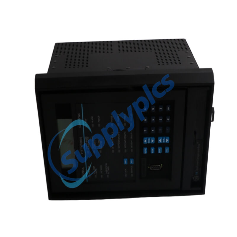
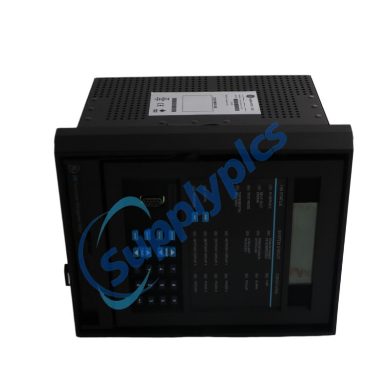
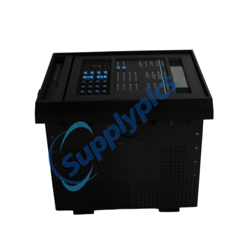
The GE 745‑W3‑P5‑G5‑HI‑A‑L‑R‑E‑H is a microprocessor‑based digital relay designed by GE Multilin for primary and backup protection of three‑winding power transformers, autotransformers, and reactors. Part of the renowned SR series, the 745‑W3‑P5‑G5‑HI‑A‑L‑R‑E‑H integrates dual‑slope percentage differential protection with second‑ and fifth‑harmonic inrush blocking, restricted ground fault detection, and comprehensive overcurrent and overexcitation (V/Hz) elements within a single drawout case. The 745‑W3‑P5‑G5‑HI‑A‑L‑R‑E‑H features an enhanced 40‑character backlit LCD, conformal coating for corrosive environments, wide‑range high‑level control power, and full Modbus/DNP 3.0 communication capability. With FlexLogic™ programmable logic, auto‑CT configuration, loss‑of‑life monitoring, and IRIG‑B time synchronization, the 745‑W3‑P5‑G5‑HI‑A‑L‑R‑E‑H delivers intelligent, maintenance‑reducing protection for demanding utility and industrial substations.
Three‑winding power transformers – primary differential protection and management for small, medium, and large units with three separate windings
Generator step‑up (GSU) transformers – comprehensive backup protection for generator‑transformer units
Autotransformers – differential and restricted ground fault protection
Reactors – overload and fault detection for shunt or series reactors
Dual‑secondary transformers – independent protection for each secondary winding
Transformers with dual‑breaker source terminals – breaker‑and‑a‑half or ring bus configurations
Substation automation – stand‑alone or integrated into bay‑level control systems
Industrial power distribution – refineries, chemical plants, steel mills, data centers
Renewable energy plants – solar, wind, and hydro power transformers
Critical grid infrastructure – where high reliability and rapid fault clearance are required
Three‑winding differential protection – dual‑slope percentage differential (87T) with independent slope‑1 (15‑100%), slope‑2 (50‑100%), and adjustable kneepoint (KP) for superior sensitivity and through‑fault stability
Adaptive harmonic inrush blocking – second harmonic, second+5th, and energization‑based restraint methods prevent maloperation during magnetizing inrush while maintaining speed for internal faults
Fifth harmonic overexcitation inhibit – dedicated element blocks differential tripping during V/Hz overexcitation events
Unrestrained instantaneous differential – trips without intentional delay for heavy internal faults to limit equipment damage
Restricted ground fault (RGF) – zero‑sequence differential for sensitive detection of low‑magnitude ground faults in star‑connected windings
Full overcurrent suite – phase, neutral (3I₀), ground, and negative‑sequence elements with IOC/TOC curves: IEEE, IEC, GE IAC, definite time, and FlexCurves™
Auto‑CT configuration – all CTs connected wye; relay automatically corrects phase angle, magnitude, and zero‑sequence compensation without external interposing CTs
Dynamic CT ratio mismatch correction – monitors and compensates for on‑load tap changer (OLTC) variations in real time
Transformer loss‑of‑life monitoring – estimates hottest‑spot temperature, aging factor, and remaining insulation life per IEEE C57.91‑1995 / C57.96‑1989
Comprehensive frequency protection – underfrequency (2 elements), overfrequency (1 element), frequency rate‑of‑change (4 elements) for advanced load shedding
Voltage protection suite – overexcitation (V/Hz) with definite‑time or IEC curves, undervoltage, and overvoltage elements
Four independent setting groups – selectable via logic inputs, front panel, or communications for different system configurations
FlexLogic™ programmable logic engine – user‑defined protection and control schemes (interlocking, dynamic setting group changes, permissive tripping) without external wiring
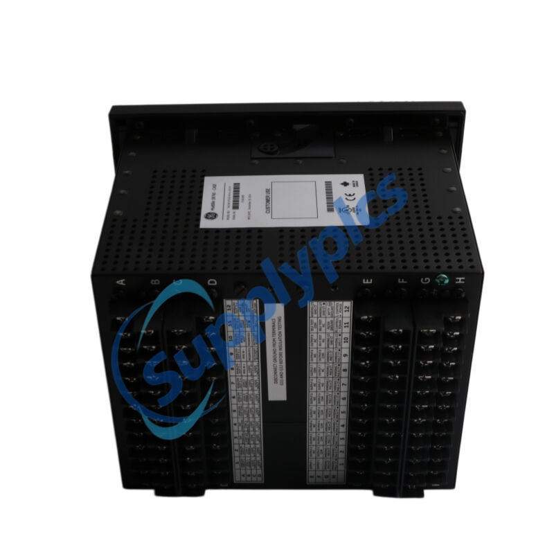
Fully drawout case with automatic CT shorting – relay portion slides out for bench testing or replacement without de‑energizing the main circuit, minimizing downtime
Conformal coating (-H suffix) – factory‑applied polymer layer protects PCB from humidity, airborne contaminants, and mild chemical corrosion for harsh industrial environments
High‑resolution 64 samples/cycle sampling – enables harmonic analysis up to the 21st harmonic, THD calculation, and harmonic derating factor (ANSI/IEEE C57.110‑1986)
Field‑upgradeable firmware – new features and updates can be added in the field without replacing hardware
Simulation mode with waveform playback – test relay logic and settings by injecting arbitrary waveform data from computer‑generated files
High‑speed event and fault recording – 128 time‑tagged events (1 ms resolution), 10 oscillography records (32 power cycles each, COMTRADE format), and data logger for post‑event analysis
IRIG‑B time synchronization – GPS‑synchronized timestamping across substations for coordinated event analysis
Multi‑port communication – front RS232 for local laptop connection; dual rear RS485/RS422 ports (Modbus RTU, DNP 3.0 Level 2); optional 10BaseT Ethernet (Modbus TCP/IP)
EnerVista 745 Setup software – single environment for configuration, monitoring, diagnostics, waveform viewing, and event retrieval; supports offline setpoint file creation and management
Security audit trail – logs all configuration changes for regulatory compliance and troubleshooting traceability
Wide‑range control power (HI) – 90‑300 V DC or 70‑265 V AC, 48‑62 Hz, eliminating external converters for retrofit projects
40‑character enhanced backlit LCD and keypad – intuitive local navigation through setpoints, actual values, and target messages
20 LED status indicators – real‑time visual feedback for relay health, system status, and trip/alarm conditions
Security password protection – restricts unauthorized setpoint changes and tampering
Harmonic monitoring – measures individual harmonics up to the 21st, THD (IEEE 519‑1986), and Harmonic Derating Factor
Detects internal transformer faults – compares differential current against dual‑slope bias with harmonic restraint (2nd, 2nd+5th, energization‑based), issuing trip commands while ignoring inrush and overexcitation
Clears high‑magnitude faults rapidly – unrestrained differential element trips without intentional delay for heavy internal faults to limit equipment damage
Senses low‑magnitude ground faults – restricted ground fault (zero‑sequence differential) detects faults close to the neutral point in star‑connected windings
Provides backup overcurrent protection – phase, neutral, ground, and negative‑sequence IOC/TOC elements with selectable curve shapes (IEEE, IEC, IAC, FlexCurves™) for coordination with downstream devices
Prevents core overheating – V/Hz overexcitation protection (2 elements) with definite‑time or IEC curves
Supports load shedding and islanding detection – underfrequency (2 elements), overfrequency, and frequency rate‑of‑change (4 elements) elements with programmable thresholds
Monitors transformer asset health – calculates hottest‑spot temperature, aging factor, and remaining insulation life per IEEE standards for predictive maintenance planning
Executes custom automation logic – FlexLogic™ engine performs local interlocking, dynamic setting group switching, and permissive tripping without external relays or PLCs
Records fault and sequence‑of‑events data – captures 128 time‑tagged events (1 ms accuracy), 10 oscillography records (32 power cycles), and data logs; retrievable via front panel or EnerVista software
Automatically configures CT inputs – corrects phase angle, magnitude, and zero‑sequence compensation automatically for simplified transformer setup
Synchronizes to GPS time – IRIG‑B input enables precise timestamping across the substation for coordinated event analysis
Communicates with SCADA/DCS – transmits real‑time metering data, protection status, fault records, and oscillography via Modbus RTU, DNP 3.0 Level 2, or optional Modbus TCP/IP
Enables offline relay testing – simulation mode allows waveform playback without applying live power, verifying protection logic before commissioning
Q1: What does the W3 designation in the 745‑W3‑P5‑G5‑HI‑A‑L‑R‑E‑H part number signify?
A1: The W3 indicates the 745‑W3‑P5‑G5‑HI‑A‑L‑R‑E‑H is configured for three‑winding transformer applications, providing differential and restricted ground fault protection across all three windings, whereas W2 is intended for two‑winding transformers.
Q2: Does the 745‑W3‑P5‑G5‑HI‑A‑L‑R‑E‑H require external interposing CTs for transformer configuration?
A2: No. The 745‑W3‑P5‑G5‑HI‑A‑L‑R‑E‑H features auto‑CT configuration – all CTs are connected in wye, and the relay automatically corrects phase angle, magnitude, and zero‑sequence compensation for over 100 transformer types, eliminating the need for external interposing CTs.
Q3: What is the benefit of the conformal coating (-H suffix) on the 745‑W3‑P5‑G5‑HI‑A‑L‑R‑E‑H?
A3: The ‑H suffix indicates conformal coating, a factory‑applied polymer layer that protects the PCB from humidity, chemical contaminants, and corrosive atmospheres, making the 745‑W3‑P5‑G5‑HI‑A‑L‑R‑E‑H suitable for harsh industrial environments such as chemical plants, refineries, and coastal substations.
Q4: Can the 745‑W3‑P5‑G5‑HI‑A‑L‑R‑E‑H be removed for maintenance without shutting down the transformer?
A4: Yes. The 745‑W3‑P5‑G5‑HI‑A‑L‑R‑E‑H is a fully drawout unit with automatic CT shorting contacts – the relay portion slides out of its companion case for bench testing or replacement while the companion case remains installed and the main circuit stays energized, significantly reducing maintenance downtime.
Q5: What software is used to configure and monitor the 745‑W3‑P5‑G5‑HI‑A‑L‑R‑E‑H?
A5: The EnerVista 745 Setup software, included with every relay, provides a single Windows‑based environment for configuration, real‑time monitoring, diagnostics, waveform analysis, event retrieval, and offline setpoint file management (supports Microsoft Windows 95 or higher).
Inguiry Now: [email protected]