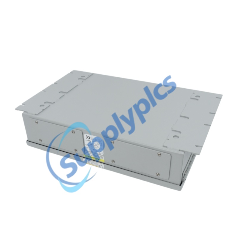
Product Name:input model
Brand Name: WOODWARD
Model Number: 8200-203
Country of Origin: USA
Warranty: 12 Months
Whatsapp:+86 18159889985
Email:[email protected]
Brand Name: |
WOODWARD |
Model Number: |
8200-203 |
Country of Origin: |
USA |
Packaging Details: |
Original new Factory Sealed |
Delivery Time: |
Delivery time in stock |
Payment Terms: |
T/T |
Supply Ability: |
in stock |
|
Sales Manager: |
Stella |
|
Send an email: |
|
|
Contact in Whatsapp: |
|
Parameter |
Specification |
|
Model |
8200-203 |
|
Manufacturer |
Woodward |
|
Product Family |
ProTech 203 Overspeed Protection System |
|
Product Type |
Digital overspeed trip device / Safety Instrumented System (SIS) |
|
Trip Logic |
De-energize-to-trip (fail-safe) |
|
Voting Architecture |
2-out-of-3 (2oo3) hardware voting |
|
Input Voltage |
|
|
Power Consumption |
12.5 VA @ AC / 4.77 W @ DC |
|
Speed Sensing Frequency Range |
|
|
Trip-Point Frequency Range |
|
|
MPU Input Amplitude |
1 Vrms minimum @ 100 Hz to 25 kHz; 2 Vrms minimum @ 25 kHz to 32 kHz |
|
MPU Input Impedance |
2 kΩ |
|
Speed Sensing Channels |
3 independent magnetic pickup (MPU) inputs |
|
Total Response Time |
40 ms maximum |
|
Accuracy |
±(0.05% × Trip Point + 2 Hz) |
|
Sample Time |
5 ms |
|
Operating Temperature |
|
|
Display Operating Temperature |
–15°C to +60°C (+5°F to +140°F) |
|
Enclosure Rating |
|
|
Dimensions (W × H × D) |
19″ × 12.244″ × 5.62″ (with knob and key) |
|
Weight |
|
|
Remote Reset |
|
|
Certifications |
|
|
Hazardous Area |
Suitable for European Zone 2, Group II (ATEX EN60079-15) |
|
Compliance |
EMC Directive 89/336/EEC, Low Voltage Directive 73/23/EEC, ATEX 94/9/EEC |
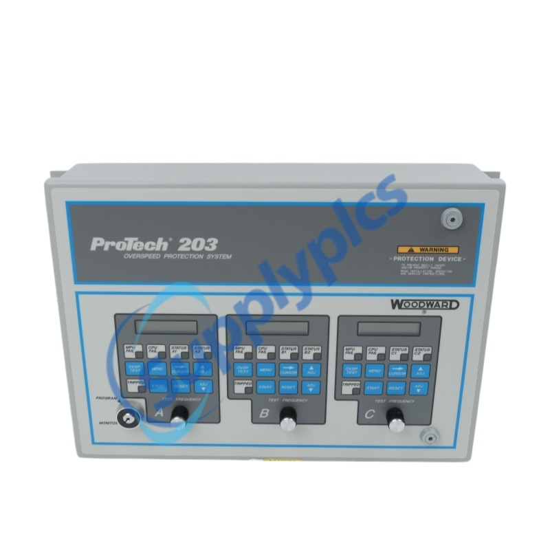
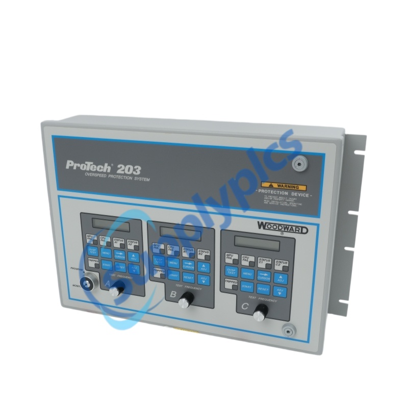
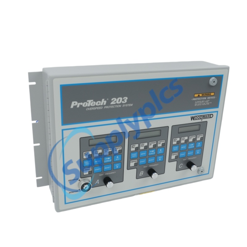
The 8200-203 is a digital overspeed protection system from Woodward's ProTech 203 series, engineered as a dedicated safety instrumented system for gas turbines, steam turbines, and other high-speed rotating machinery . The 8200-203 monitors prime mover speed through three independent magnetic pickups (MPUs) and executes a 2-out-of-3 voting logic to initiate emergency shutdown when two of three channels confirm an overspeed condition . The 8200-203 features de-energize-to-trip fail-safe design, ensuring that loss of control power results in a safe (tripped) state rather than a dangerous failure mode . The 8200-203 offers front-panel configuration, hot-swappable modules, and NEMA 4/4X enclosure for demanding industrial environments .
Triple-Redundant Architecture with 2oo3 Voting – Eliminates single points of failure; a single sensor or channel failure cannot cause either a spurious trip or a failure to trip . This architecture aligns with SIL requirements for critical machinery protection .
De-Energize-to-Trip Fail-Safe Design – Loss of control power, internal faults, or wiring failures result in a safe (tripped) state. Woodward strongly recommends this configuration for general safety .
Hot-Swappable Modules – Each speed-sensing unit can be replaced while the other two units remain powered and operational, eliminating costly downtime .
Built-In Self-Test Capability – On-board frequency generator permits testing of each unit individually while the prime mover remains on-line .
Superior Accuracy Over Mechanical Devices – Digital speed sensing and indication achieve accuracy to within 0.1%, far exceeding the capabilities of mechanical overspeed devices .
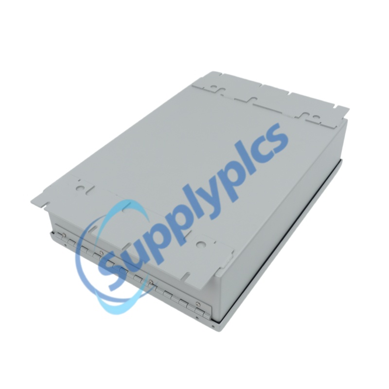
Harsh Environment Ready – NEMA 4/4X (IP54/IP65) enclosure with lockable front panel prevents unauthorized modification of safety settings .
Three Independent Speed-Sensing Units – Each with its own separate power supply, continuously monitoring prime mover speed
2-out-of-3 Hardware Voting Logic – Six voter relays configured in a series/parallel arrangement; two units must trip to initiate a turbine shutdown
De-Energize-to-Trip (Fail-Safe) Logic – Interposing relay energized during normal operation; de-energizes on overspeed or power loss
Front-Panel Operator Interface – Touchpad with two-line by 16-character LCD display; Menu, Cursor Right, Adjust Up, and Adjust Down keys
Keyswitch-Protected Programming – Prevents unauthorized configuration changes; MONITOR mode for normal operation, PROGRAM mode for configuration
Built-In Frequency Generator – Enables overspeed testing of each unit individually without taking the prime mover off-line
Comprehensive LED Status Indicators – Trip, MPU failure, CPU failure, voter relay status, and power supply status indicators
Peak Speed Recording – Captures and stores maximum speed during overspeed events in non-volatile memory
MPU Failure Management – Programmable MPU fail setpoint and timeout; configurable trip-on-failure option
Remote Reset Capability – Allows reset from a remote location via field wiring
Lockable Enclosure – IP54/NEMA 4 rated for industrial environments without additional climate control
Continuous Speed Monitoring – Each of the three speed-sensing units reads its respective MPU signal and calculates rotational speed every 5 ms
Overspeed Detection – Compares measured speed against configurable trip setpoint (typically 110–115% of rated speed); triggers trip when two of three channels confirm overspeed
Loss-of-Signal Detection – MPU failure detection when frequency drops below 100 Hz after previously exceeding 120 Hz; programmable alarm-only or alarm-plus-trip response
MPU Fail Timer – Start-up timer ensures speed exceeds MPU fail setpoint within programmed timeout; otherwise trips the prime mover
Voter Relay Actuation – Each speed-sensing unit actuates two voter relays; six relays configured in series/parallel drive the interposing relay
Trip Relay Control – Interposing relay provides two normally open and two normally closed contacts for integration with external actuating systems
Built-In Self-Test – On-board frequency generator allows overspeed testing of individual units while system remains on-line
Peak Speed Storage – Updates and stores peak speed in non-volatile memory when overspeed occurs
Alarm Annunciation – Separate alarm output and LED indicate individual unit trip status; MPU failure and CPU failure LEDs provide diagnostic information
Hardware Fault Detection – Continuous monitoring of EEPROM, interlock signals, and microprocessor function; trip on hardware fault detection
1: What are the input power requirements for the 8200-203?
A1: The 8200-203 accepts 120 Vac/dc input, with an operating range of 88–132 Vac or 90–150 Vdc. Power consumption is 12.5 VA for AC operation and 4.77 W for DC operation .
Q2: What is the difference between de-energize-to-trip and energize-to-trip models?
A2: In de-energize-to-trip models like the 8200-203, the trip relay is energized during normal operation and de-energizes on overspeed or power loss—ensuring a safe (tripped) state if control power is lost . Woodward strongly recommends de-energize-to-trip for general safety . Energize-to-trip models require power to trip and may not trip on power loss.
Q3: Can individual units be replaced without shutting down the turbine?
A3: Yes. The ProTech 203 system features hot-swappable modules. Each speed-sensing unit can be replaced while the other two units remain powered and operational, allowing on-line maintenance without tripping the prime mover .
Q4: What is the speed sensing frequency range of the 8200-203?
A4: The speed-sensing frequency range is 100 Hz to 32 kHz, with a trip-point frequency range of 250 Hz to 25 kHz. The minimum MPU input amplitude is 1 Vrms from 100 Hz to 25 kHz, and 2 Vrms from 25 kHz to 32 kHz .
Q5: How does the 2-out-of-3 voting logic improve system reliability?
A5: The 2-out-of-3 voting logic requires two of three independent speed-sensing channels to detect an overspeed condition before a trip is initiated. This eliminates single points of failure—a single sensor failure cannot cause either a spurious trip or a failure to trip, significantly enhancing system reliability and preventing unnecessary downtime .
 EN
EN